N6OCS
The Nucleus Transmitter
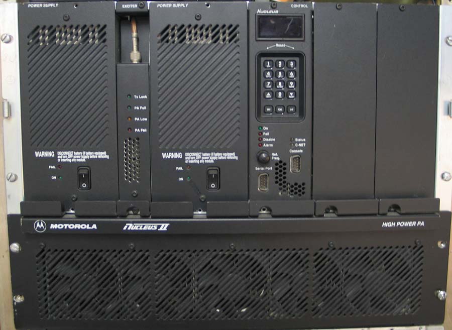
A "stock" C-net Nucleus Paging station
The N6OCS repeater is based on a Motorola Nucleus II 900 MHz paging station with c-net control for the transmitter, power amplifier, power supplies and mounting chassis. While there are less expensive ways to build a 900 repeater, the Nucleus seems like a great choice. The Nucleus II is a 300 watt station designed to run 24/7 at full power, so with it turned down to 100 watts it should cruise along with a high degree of reliability. Since it was designed to operate in the harsh environment of a commercial site with a lot of RF noise it should be immune to some of the intermod problems that can plague lesser radios. The Nucleus also has a very stable oscillator and time base section that can be disciplined from an external source. At this time the station's time base is derived from a Trimble "Thunderbolt" GPS receiver. This provides an extremely accruate frequency output. Although the Nucleus is a bit power hungry it seems to be a clear cut choice over a modified mobile radio.
Modifications to the Nucleus is fairly simple and non-intrusive.
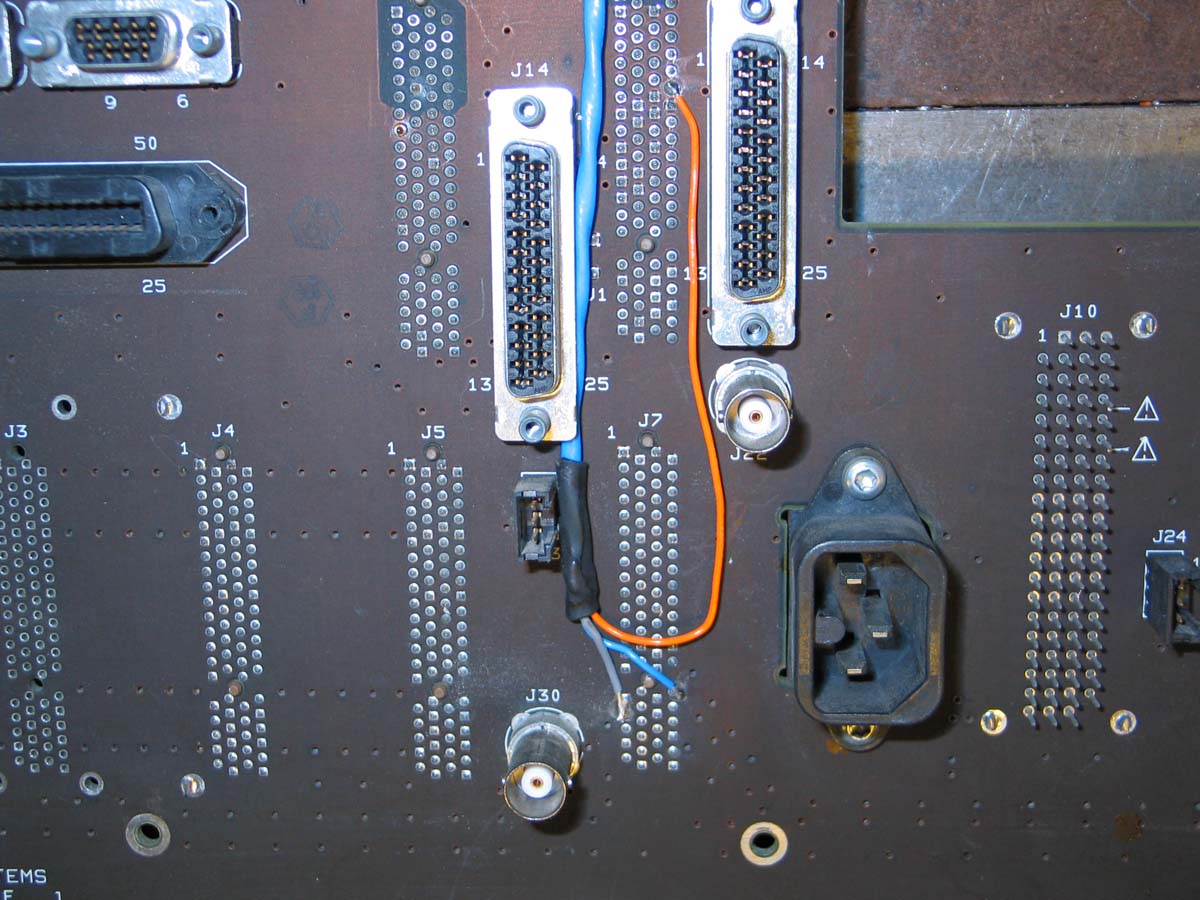
The Nucleus used in this project is the C-net version which requires a few modifications. The Nucleus modifications are fairly straight forward and require three connections to the back plane and one trace cut on the SCM board. My goal was to keep the Nuc as unmolested as possible so it would remain modularized for service.
I soldered a lead (grey wire) to the shield then covered it with heat shrink and soldered the other end to pins 57 & 61 of J7 for the ground. I used 2 ground pins here for strain relief. It appears that all of the ground pins on these connections have square solder pads and all others are round.
The orange lead is soldered to pin 24 on J8. This is the external key line. You can also find it on pin 10 of J17, the 50-pin telco connector. This line needs to be pulled low to key up the transmitter. However it can be selected as a pull high from the command menu. I set mine for low. The Nuc draws about 180 ma to pull down this line so I installed a simple relay to take the load off the controller.
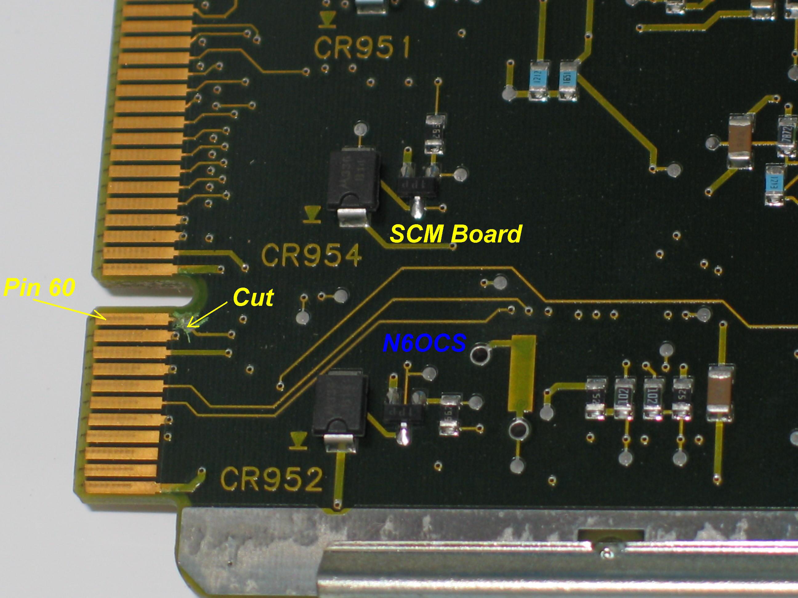
The blue wire is the audio input to the exciter and is soldered to pin 60 of J7. Audio and PL are inserted here together. You can also pick this off at Pin 78 on J9 . I choose J7 because it was closest to the J8 connector and I didn't want to have wires running all over the place. This is straight forward except the SCM board puts a heavy, low impedance load on this line. The best solution that I came up with was to cut the trace on the SCM board from pin 60. This is easily repairable and easily repeatable on spare SCM boards.
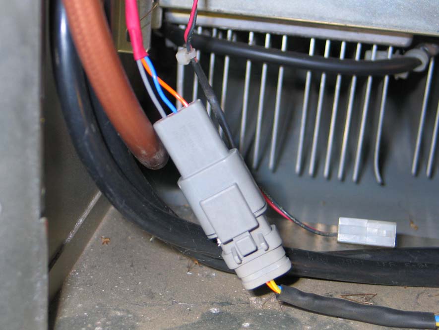
The Nucleus interface connector is a 3 pin, female DTC connector. Pin 1 = ground (black), pin 2 = audio (blue),pin 3 = PTT (orange). The controller end is male.
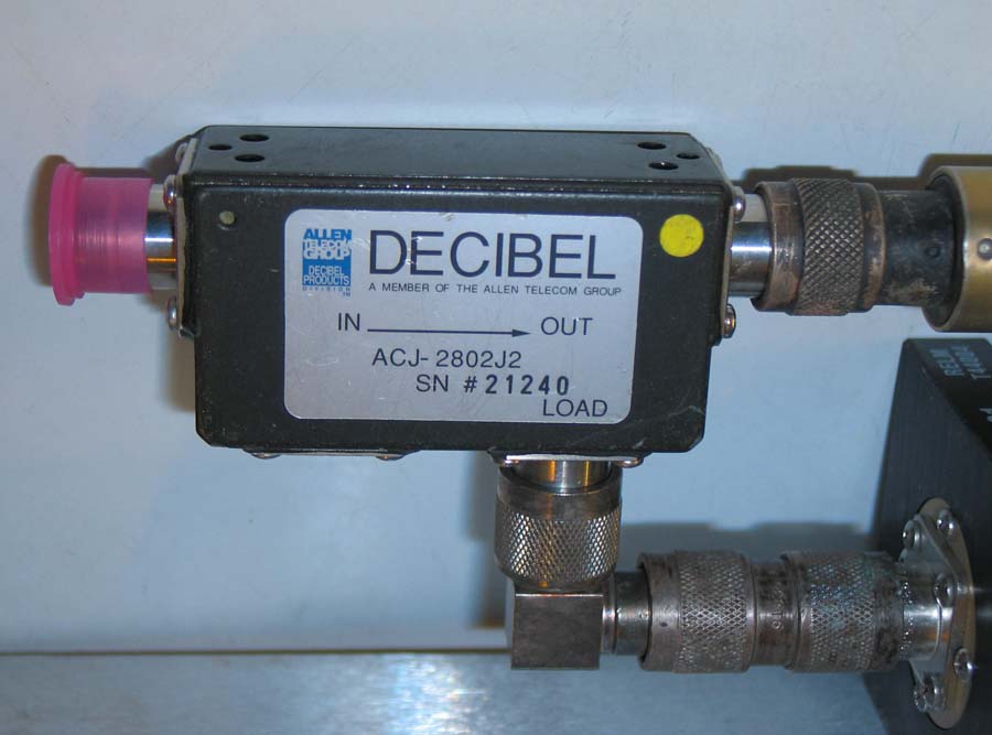
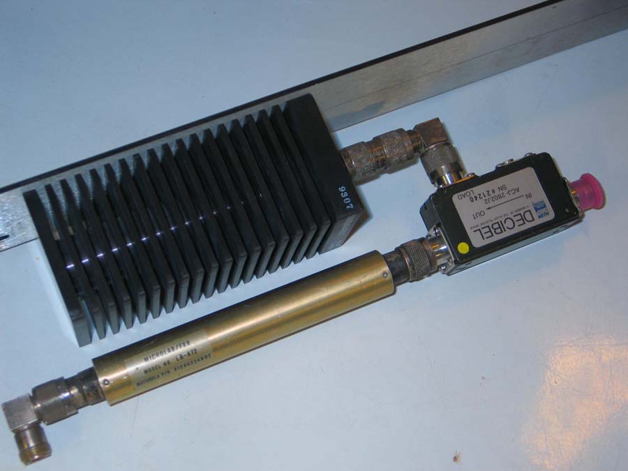
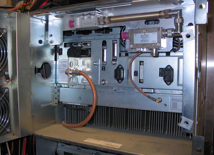
The image on the left is the double circulator or isolator. The photo on the right is the isolator, load and low pass filter assembly
Nucleus Configuration:
The default front panel password is "6000". This can be changed once you gain access to the system. You can also completely disable it for convience. If "6000" does not gain you access, keep reading!
The SCM has a 4-pole DIP-switch located near the lower front edge of the circuit board. This switch is read when the station is powered up or on a "reset".
Switch #1 (the one closest to the front panel) turn On to allow changes in frequency programming. When this switch is on, the display will show "FREQ PROG ENABLED" during boot-up. I leave it turned on all the time so I can change frequencies at will.
Switch #2 is turned ON to completely reset the station's settings to default, this includes the front panel password, all frequencies, power settings, options, etc. With the power off, pull off the front panel and flip switch 2 on then turn on the station power. When the station finishes initializing, turn off the power, turn off switch 2, replace the control panel, and turn the power back on. The station will be in factory default mode and will now accept the "6000" password. The password can be turned off by pressing STN, then down-arrow three times to get to FRONT PANEL PASSWORD, then ENTER, then TOG to set it to DISABLED, then ENTER, then EXIT
You will need to set the Nucleus for Kxternal Key to use the EXT KEY REQ input and it will be active LOW. This is the orange wire listed above on pin 24 of J8. To do this, gain access to the system if necessary you may have to enter the password and press the CNFG button. Now press the up-arrow button once to reach the menu choice that says SPECIAL KEY SELECT, press ENTER, then press the up-arrow button twice to reach EXT LOW. Press ENTER to select EXT LOW, now press EXIT several times to get out of the menu.
Frequency selection:
You can tell the transmitter frequency range by pressing the STN button. The first message that comes up is "TX FREQ RANGE: ____ MHZ".
Note that this is read-only and cannot be changed at this point but, you can bypass the frequency range limit restriction.
From the top menu, press STN, press the ALGN button twice; TX RANGE CHECKING ENABLED should appear. Press ENT, then
TOG to disable the option, then ENT to save it. Then EXIT. You can now enter Ham frequencies that are outside the normal limits
for the station.