Spectra Mods
VCO Mods
My preferred mobile radio is Motorola's top of the line, Spectra. Even though the Spectra is no longer produced or supported by Motorola, the 900 MHz version offers Motorola quality of construction, 30 watts, 128 channels, a text display, and there are a bunch of them out there. Not all Spectra's will do all the above so be careful what you buy. Because the noise floor in Southern California is so high having 20 to 30 watts is a good thing.
There several great sources of information on the Spectra radio so I won't try to duplicate all of that good work, but rather touch on some items that have worked well for me.
A good place to start is BatLabs http://www.batlabs.com/spectra.html but before you fire up the soldering iron to modify the VCO read on. http://onfreq.com/syntorx/spectra/index.html is another good site and Repeater Builders at http://www.repeater-builder.com/motorola/spectra/spectra-index.html is an excellent resource. The bottom of this page has a bunch of very helpful links
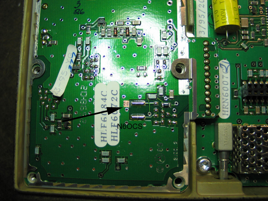
Now that I've pointed you to all the hotspots here is my 2 cents worth. There is only one hardware modification to the radio that needs to be made in order to have the VCO lock down in the ham band and there are two methods of modifying the VCO to make it work. First, is the Batlabs method of modifying the length of the striplines. In reality this is probably the "proper" way to do it. However, getting the steering voltage to fall into the proper range for the ham band can be accomplished by the simple addition of a 221K resistor (give or take a few K). This is an easy quick fix and gets the job done very well.
So, here is my 10 minute modification. I use a SMD resistor 221 K ohms. First remove the bottom cover with the 2 torx screws. This is the larger of the two covers. The other one covers th PA. Next remove the 6 screws on the cast cover, this will expose the solder side of the VCO Board. You may have to remove the paper tag to get access to the ground plane area of the board. Using an ex-acto blade, scrape away some of the green surface coating as seen here.
Before
Tin the newly exposed copper surface with the help of some liquid flux, but be sure to remove as much solder as possible so as not to leave a glob on the new pad. This is so the SMD will sit flush against the board. Next, wet the SMD chip resistor with the liquid flux and let it dry for a minute. This will make it a bit tacky. With a pair of tweezers and a toothpick place it in position as shown in the photo.
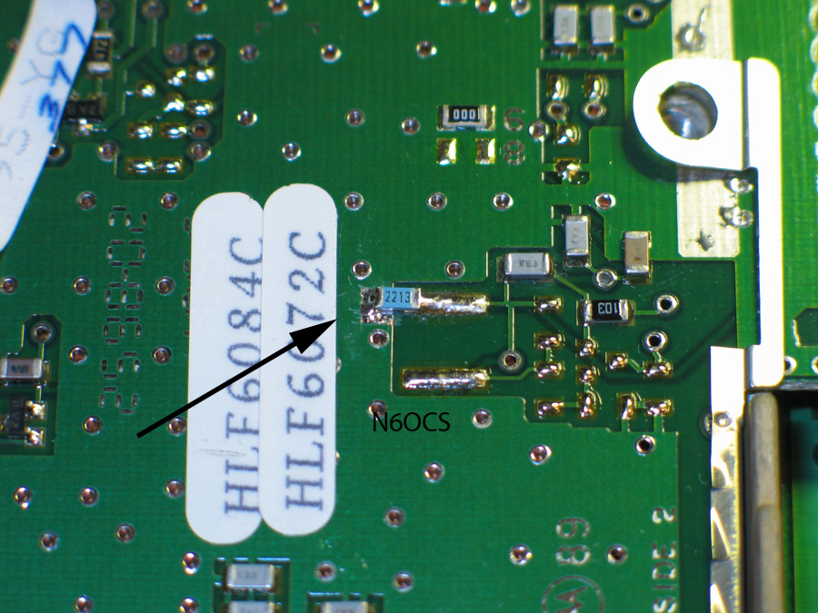
After
While holding down the center of the resistor with the toothpick, using a small, chisel tipped, iron set to about 650 degrees f, touch the soldering iron to the right end of the chip just long enough to flow the existing solder onto the chip. Then using a little solder, flow some solder onto the new pad. This side may take a bit more heat as the ground plane will soak up a fair amount. Once you have a nicely flowed joint on either side, you’re done. You should probably check the steering voltage at this point as described in the other articals. If all is well, button the radio back up and fire it up.
Two alternate resistor methods have been used. One is using the same SMD resistor but off to the side of the strip to one of the plated through holes. Saves time. The other is using a 1/8th watt resistor with leads. You just have to watch the clearance with the cover.
Capacitor Replacement
There is a small mention of front panel display going bad or dimming. On the display board there are two metal can electrolytic caps that often leak and can foul the board as well as fail. When they fail the display goes dim or out. Even radios that are "brand new old stock" have had some failed electrolytics due to age so I just replace them with tantalums while I'm in the radio making other modifications. I've been replacing them with surface-mount capacitors but you have to be VERY careful removing the old caps.
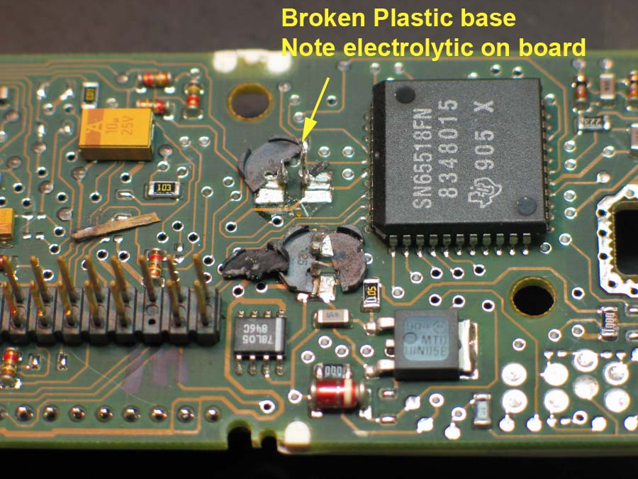 I destroy the old cap by prying the can off its leads between
the plastic insulator and the can, then I carefully break off the plastic insulator and clean the board with isopropyl
alcohol or contact cleaner, THEN unsolder the two leads from the pads on the board. This causes less stress on the
board pads. I use an 18 watt small iron, a stereo microscope and light. Another secret is to use liquid flux on the
end of a very small screwdriver or toothpick to flux the pads as well as the new part."
I destroy the old cap by prying the can off its leads between
the plastic insulator and the can, then I carefully break off the plastic insulator and clean the board with isopropyl
alcohol or contact cleaner, THEN unsolder the two leads from the pads on the board. This causes less stress on the
board pads. I use an 18 watt small iron, a stereo microscope and light. Another secret is to use liquid flux on the
end of a very small screwdriver or toothpick to flux the pads as well as the new part."
I use 4 different high temp tantalum SMDs to upgrade the spectra. I replace all the electrolytics in the radio
because I'm looking for reliability more so than cost. That's why I have Spectras to start with.
Another note. You don't really need a hot air station to INSTALL these SMD caps. Once you get the
old ones off as I described above, I install the SMDs by first cleaning the pads and then using
a toothpick to apply a small amount of liquid flux. At the same time apply a liberal amount of
liquid flux to the bottom pads of the cap. Next tin the pads on the board. Now with a small tool hold
the cap down in place on the board. Make sure you know the polarity because getting the SMD caps
back off without the hot air is a real chore. Now with a small chisel tipped, cleaned and tinned iron,
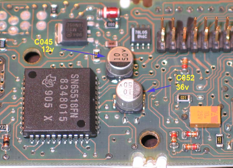
wedge the tip in between the cap and board at one end. C052 is a real chore because the new cap pretty well covers
the pads up. Once you flow the solder on one side of this cap, check the cap for movement to make sure that you have a good bond
before moving on to the other pad. Apply just enough heat to cause the tinned solder on the board to
wick up onto the caps pad. This will now hold the cap in place. Let the cap cool for a few seconds.
Next move to the other pad and repeat the procedure except this time I always add a small amount of solder to better
flow the joint. Again let the cap cool off then go back to the first joint and reflow it adding some solder for a better flow.
The big secret to this is the liberal use of liquid flux. It will clean up later with a little bit of isopropyl
alcohol but it won't hurt if you just leave it either. I also use the liquid flux and solder wick to clean the
pads after removing the scummy old caps.
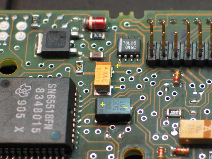
TAJC106K025R Kemet High Temp (150 10uF 25volt 10%
T498D106K50TE1K0 Kemet High Temp (150 10uF 50volt 10%
T498B106K16TE2K8 Kemet High Temp (150 10uF 16volt 10%
T495D476K20ATE175 Kemet SMD Low ESR Ta 20volt 47uF 10%
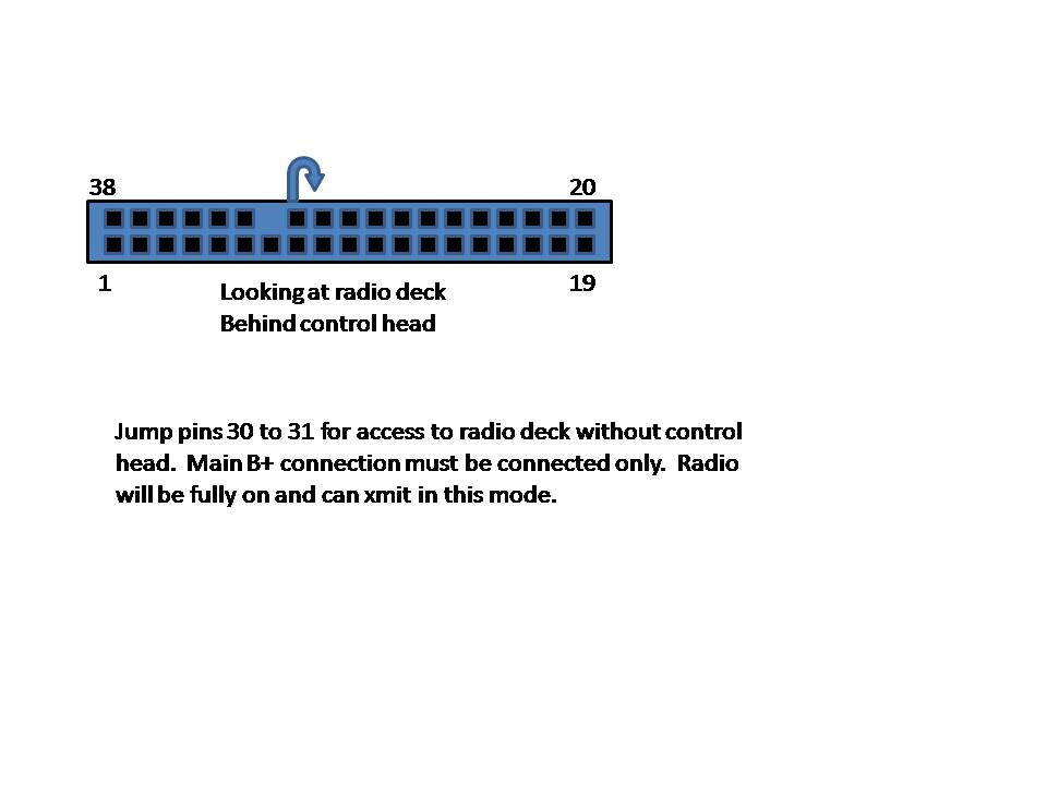
To help with trouble shooting, Refer to the drawing below. By removing the control head and adding this jumper you should be able to access the deck with your programing computer. This will help you verify the function of the deck regardless of the head condition.