Receive Filter/LNA Panel


Front Panel Photo of Receiver Filter/LNA
click for larger image (28KB)


Rear Panel Photo of Receiver Filter/LNA
click for larger image (52KB)


Bottom View of Receiver Filter/LNA
click for larger image (44KB)
To improve receive performance, an Angle Linear RF Assembly is installed between the duplexer and the receiver (Thanks to Chip, N6CA for providing the assembly). This assembly consists of two quarter wavelength cavity filters followed by a PHEMT preamplifier. The photos to the left show different views of the RF assembly.

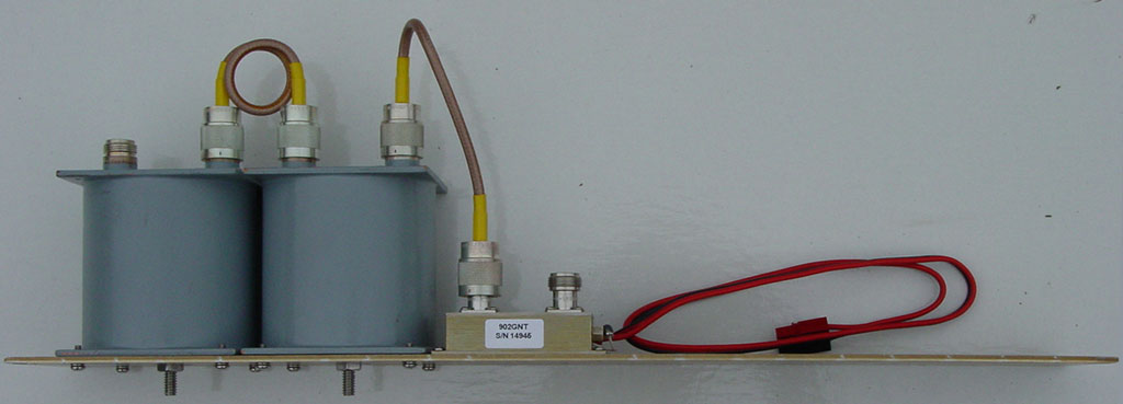
The two cavities provide the supplementary filtering required prior to the preamplifier. The PHEMT preamplifier improves overall receiver sensitivity by providing a low noise, high gain stage prior to the receiver.

Performance characteristics of the RF assembly are shown below.


Receive RF Panel Characteristics

Bandpass Filter Performance


click for larger image (28KB)
This set of plots shows the performance characteristics of the pair of cavity filters at various frequency spans. The close-in plot shows an insertion loss of approximately 1.1 dB and an input return loss of approximately 22 dB. The wideband plot shows rejection at the transmit frequency of 46 dB.

LNA Gain & Noise Figure

LNA Gain & Noise Figure Plots
click for larger image (16KB)


Shown are wideband plots of gain and noise figure for the PHEMT preamplifier. At the receiver operating frequency, the noise figure is approximately 0.7 dB with a gain of 14 dB.

LNA Current Consumption


Return to Repeater Home Page