Using the Qualcomm 1152 Board’s Power Supply
By Ed Munn, W6OYJ
August 3, 2008
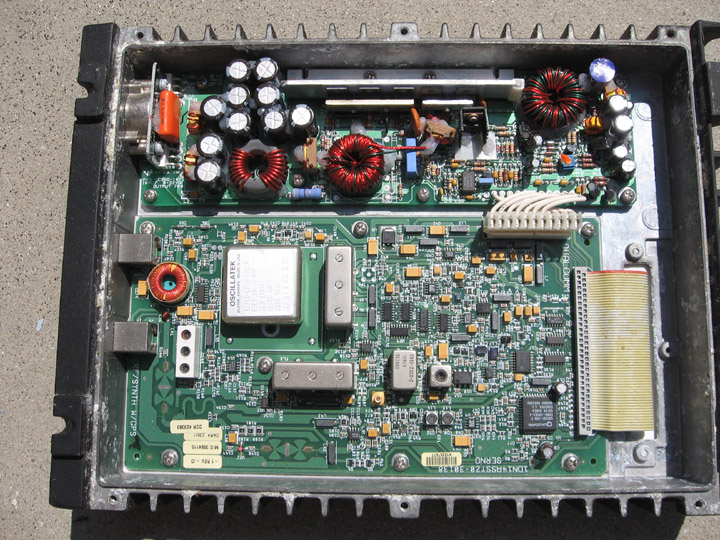
The 1152 RF Transceiver Board and its power supply board were originally mounted next to each other in the top half of a ruggedized and weatherproofed metal transceiver housing. The bottom half of this housing originally contained the digital portion of the transceiver. Most amateur uses of this unit have replaced the lower digital board and components with transverter parts for different amateur frequency bands. The following is some information specific to the power supply.
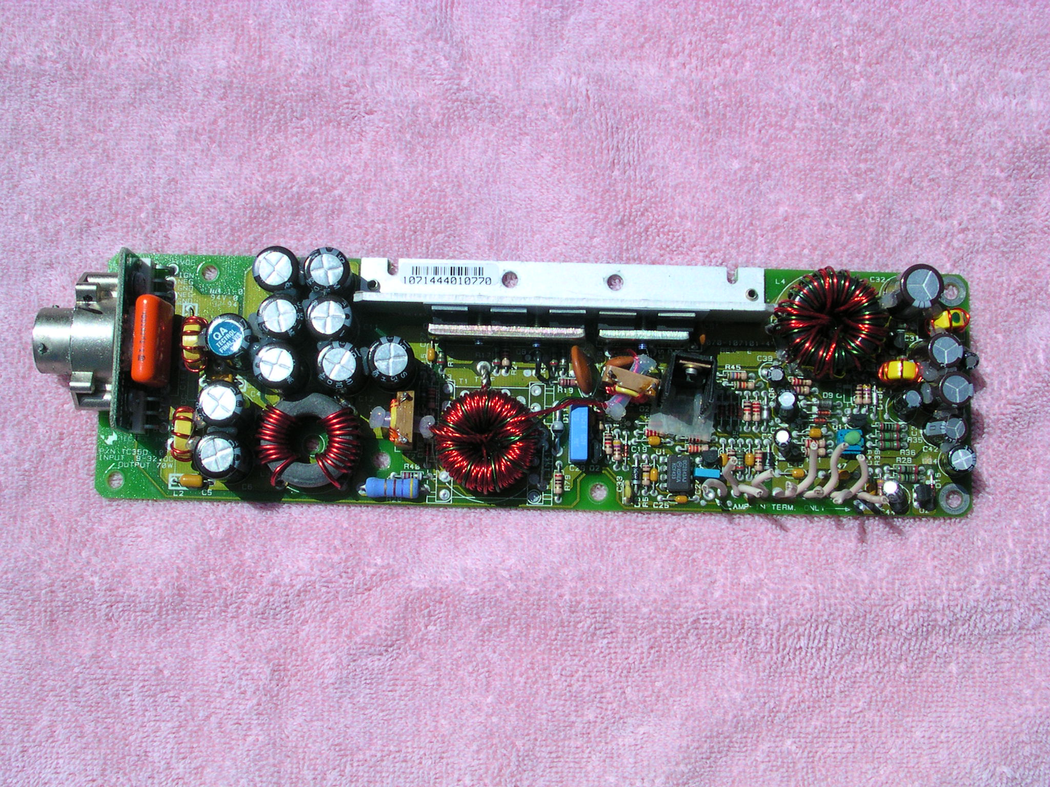
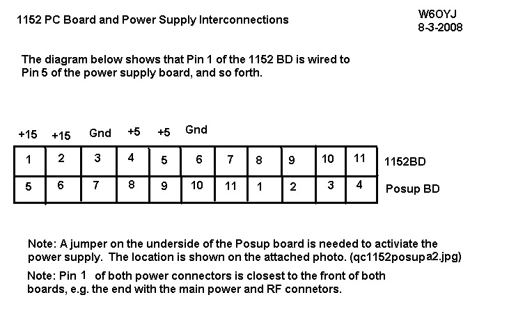
Sometimes the Power Supply board has been used to power different amateur radio projects with its +5V and +15V outputs. This meant cutting the leads between the power supply and the rf transceiver board. I have made a diagram showing the interconnection wiring between the 1152 board and the power supply.
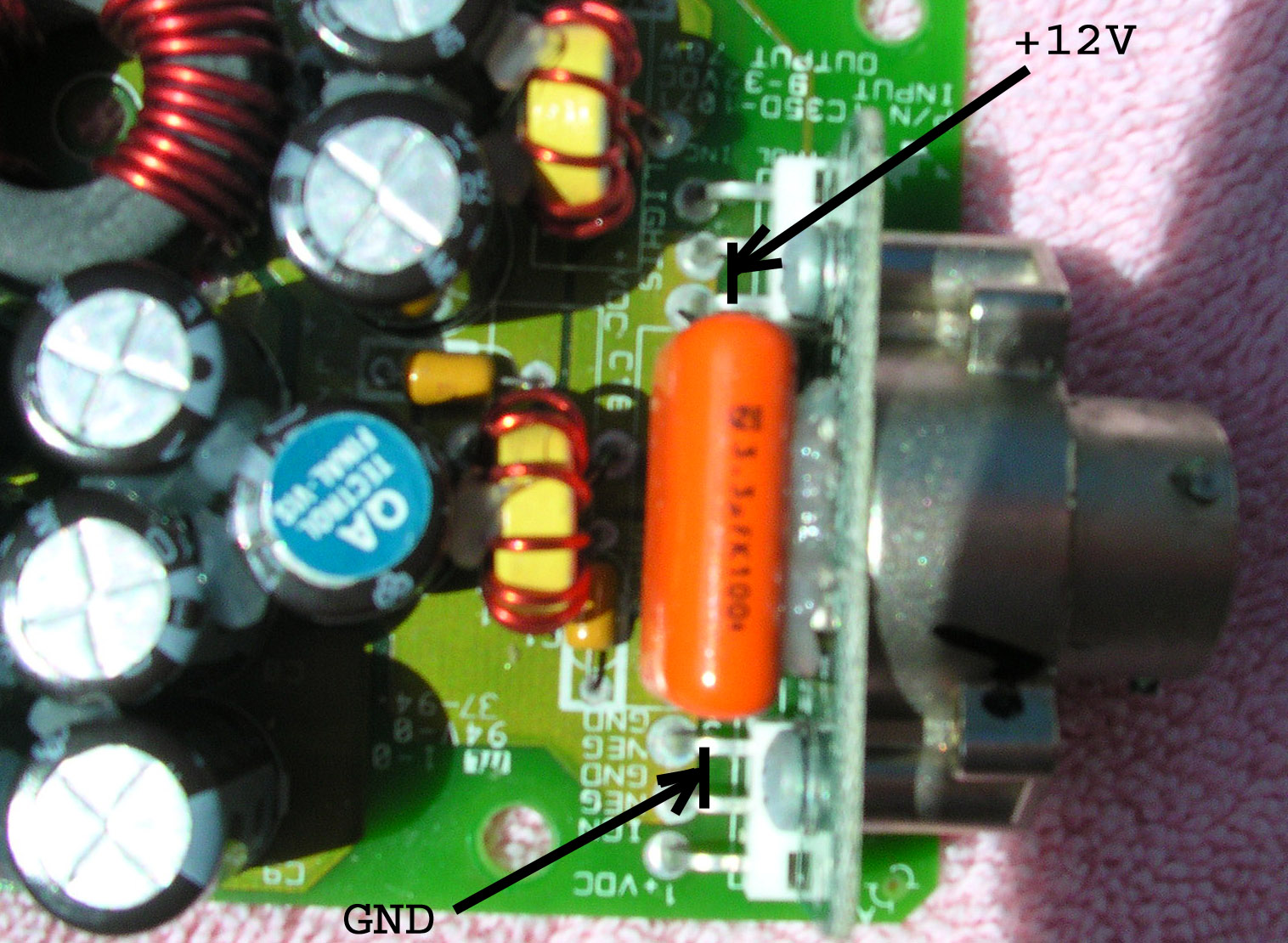
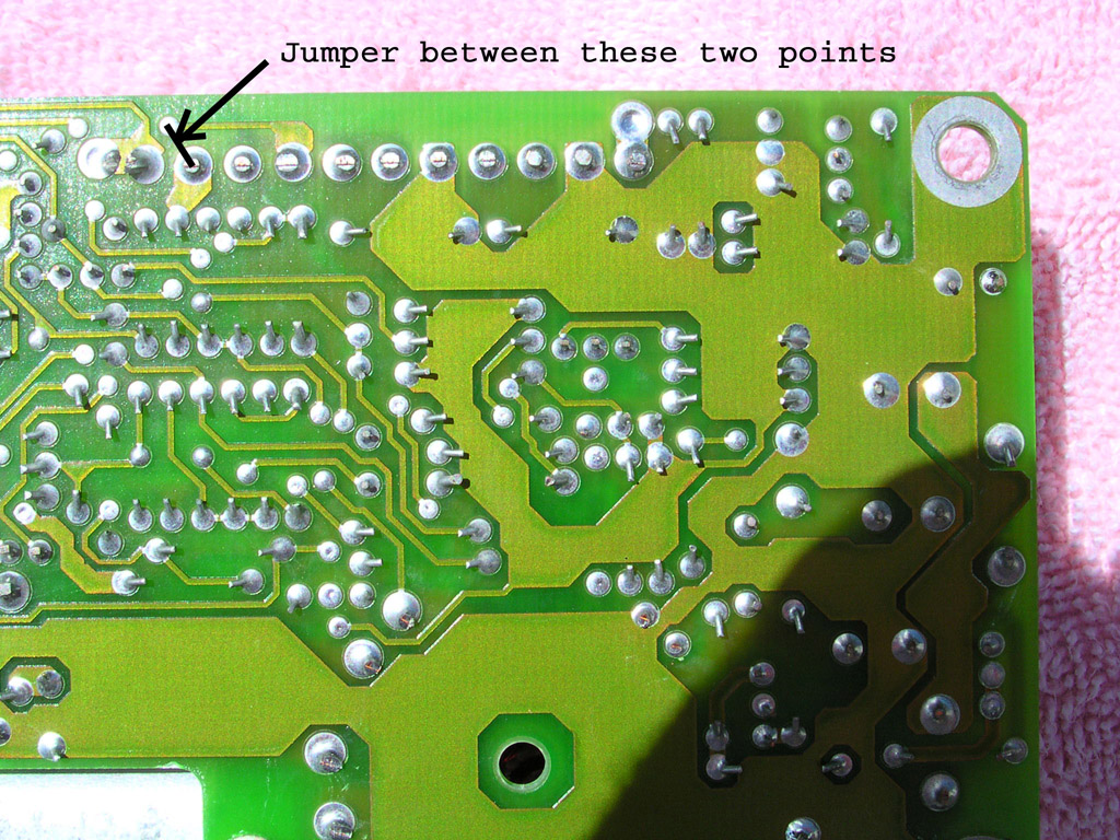
Also there are photos showing the +12V input voltage connections at the main connector of the power supply, and a jumper which may be needed to activate the power supply. It is not clear whether this jumper (on the bottom side of the power supply) is needed if the original 11 wire connections are retained between the two pc boards.
I thought we had documented this information several years ago, but apparently not. As a number of these pairs were distributed yesterday, I have rushed to get this info out without having time to test the need for the jumper.
Let me know if you have any problems.
73s from Ed Munn, W6OYJ
email: w6oyj@amsat.org