A Low Cost Noise Source for VHF through 10 Ghz Based on Qualcomm Surplus Material
K. Banke N6IZW 12/18/00
During Our November 2000 San Diego Microwave Group meeting we held a session on
noise figure
measurement. During problem solving activities in the following
weeks, it became obvious that others in our group could make good use of a calibrated
noise source. I began looking for an alternative to loaning out the noise source
used with my Sanders noise figure meter. I did a quick scan of articles on home brew
noise generators and studied in particular Paul Wade's article "Noise: Measurement
and Generation" which is available on his website as well as in the ARRL 2nd
Microwave Projects Manual.
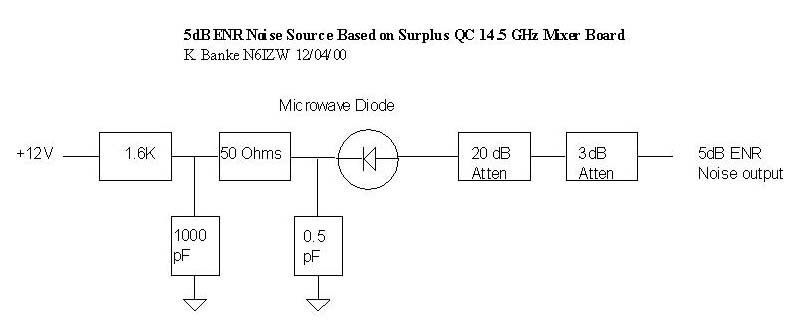
In his excellent article, Paul describes what he went through to build various homebrew noise generators, which included dismantling a commercial unit. As soon as I finished the article, an idea hit me that I felt might solve the problems of obtaining high frequency diodes and high quality microwave circuit board material as described in the article. My thought was to use a small section cut from a 14.5 GHz upconverter mixer circuit board used in the early Qualcomm Omnitraks units. This mixer is not useful at 10 GHz and is not readily modified to do so but does contain two very good microwave diodes (good through 24 Ghz) mounted on 15 mil Teflon circuit board. The circuit I decided to use is shown here.
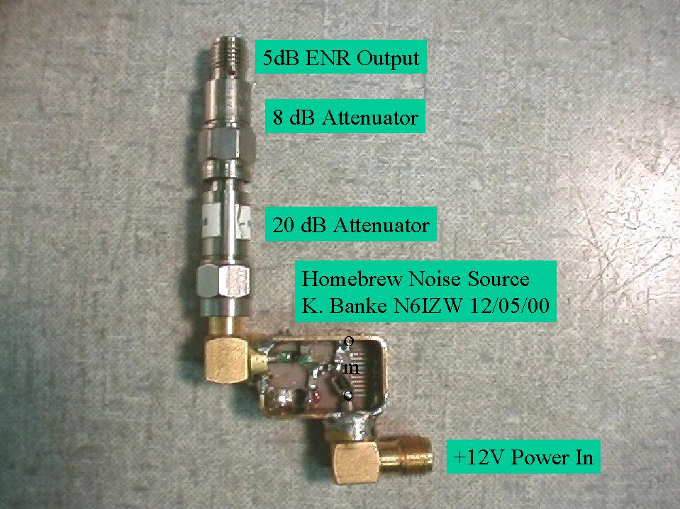
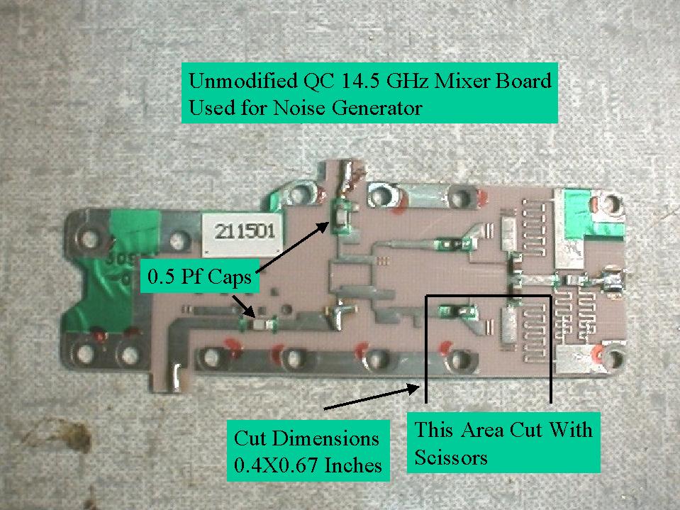
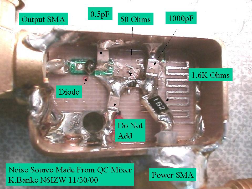
The idea was to see how well this mixer diode would perform as a broadband noise source when operated at the breakdown point with reverse bias. The pictures show the finished unit along with the original board. I used Paul's circuit which has the anode of the diode connected directly to the 20dB attenuator. The cathode is RF bypassed to ground and receives bias through a series resistor. Following Paul's article I found that for the first unit 1.2 milliampers produced the maximum output at 10 Ghz so a series resistor was selected (1.6K) to provide 1.2 ma with a 12v power supply. The next view shows the cut portion of the mixer board before adding resistors and capacitors.
Probably the most critical aspect of construction is having as short of paths to ground as possible for the RF bypassing and to the SMA output connector. The 0.5 pF capacitor needs to be a good quality microwave type and is removed from another part of the 14.5 GHz mixer board. I made the housing as small as possible to prevent unwanted resonances and also aid in good grounding. The quality of the output attenuator is also a big factor in flatness of frequency response. A close-up view of the assembled unit is shown here.
Half of the battle is building a good noise source & the other half is calibrating
it. The approach I decided to use for calibration over the 145 MHz -10 GHz Ham bands
was to use enough broad band amplification ahead of a spectrum analyzer (set for
1 dB/div) to provide a Y-Factor of about 3 dB with a source ENR of 5dB (about a 5
dB NF). My setup consisted of two, three stage MMIC amps built by removing the FETs
from QC surplus "GOLD Board" LNAs and replacing them with HP MGA-86576
devices. I found that working with two broadband amps with considerable gain creates
intermodulation products from noise when used without a filter between the amplifiers.
For 145 MHz-3456 MHz I was able to use one amplifier without a filter and controlled
the gain by varying the power supply voltage. The gain was increased only as needed
to get a Y-Factor in the order of at least 3dB. For 5.7 and 10 GHz, a filter was
inserted between the two amplifiers and the gain again adjusted to the minimum capable
of doing the job.
A goal of 5dB ENR was set as this should be useful for measurement
of most preamps in the 1- 10 dB NF range. . It was found that a total of 23 dB of
attenuation matched the output of the uncalibrated unit to the calibrated noise source
at an arbitrary frequency of 2304 MHz. Other values could certainly be used to match
the requirements of particular noise figure measuring units. My experience with the
Sanders unit is that it is quite fussy about levels and such and may give erroneous
readings unless careful attention is given to the measurement setup. For this reason
I tend to use a spectrum analyzer or power meter to measure the Y-Factor and calculate
the Noise figure. This is not very convenient though when trying to make adjustments
on the fly but allows measurement of most amplifiers and xverters.
I generated an Excel spreadsheet to aid in calibrating
against a known source. The Y-Factor was recorded for both a calibrated source (5
dB ENR) and the uncalibrated unit at each frequency of interest. The Y-Factor values
along with the ENR of the calibrated source were entered into the sheet which calculated
the ENR of the uncalibrated unit. Other approaches certainly could be used such as
using a transverter with the noise sources and measuring the Y-factor at the IF or
at the audio output of the IF radio.
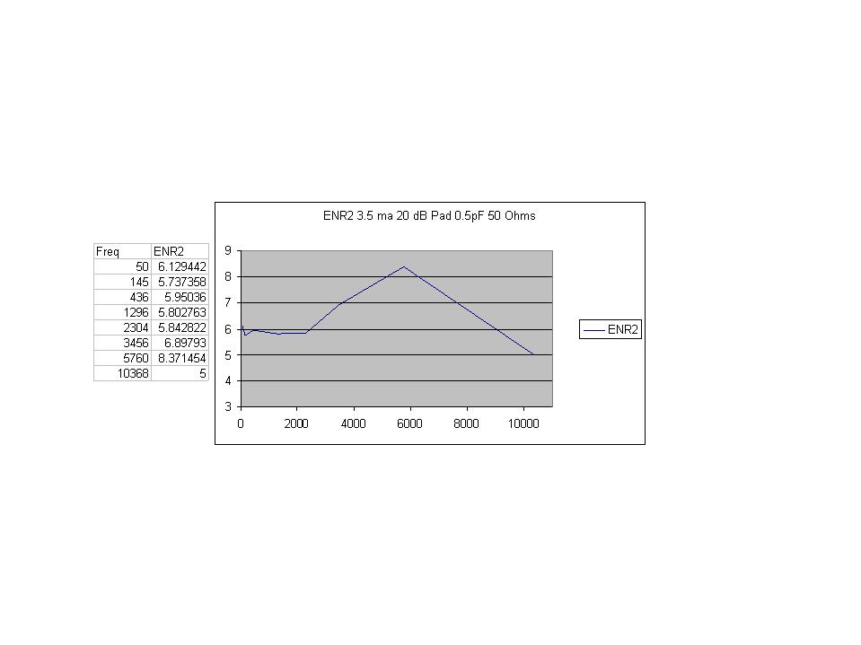
The results of the first units showed a variation of +/- 1.5 dB over the 50 MHz to 10 Ghz range. I believe that with more work the output can be made even flatter across the range.
Construction:
There are actually two useable diodes on the mixer board. Only
one is mounted as to easily accept a positive bias supply. The other can be used
either with a negative supply or can be carefully removed and re-soldered in the
opposite direction. The white dot (cathode) needs to be connected to the RF bypass/
bias network for a positive supply.
Remove the Chip capacitors from the mixer board before cutting
with a scissors. The board dimensions of 0.4X0.67 inches are not too critical
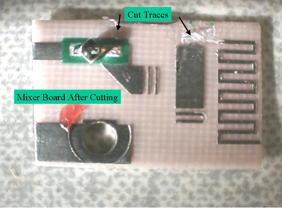
but should be followed to keep the RF paths very short. After cutting the board,
cut/remove the two traces shown in the picture. Cut the center
pin off the output SMA connector so as to not overlap onto the diode. Position &
solder the center pin onto the board trace and then solder the outside of the connector
to the bottom of the board. Use ¬' wide hobby brass which is .01-. 025 thick to make
a box around the board as shown. Position the brass & then tack in place in a
couple of locations until satisfied with the positioning. Solder the brass to the
bottom side of the board and also the output
connector. Drill a 0.065 dia hole
in about the position shown to mount the bias connector. Small coax could probably
also be run directly out of the noise generator for bias rather than using a SMA
connector.
Install the capacitors and resistors as shown. Temporarily install a 1K resistor in place of the 1.6 K resistor until the required bias current is determined. Connect a current meter in series with the 1-k resistor and a variable supply. Turn on the supply and increase the voltage until the current reaches about 1 milliamperes.
Connect the noise generator output through about 25 dB of attenuation to the setup which will be used to calibrate the ENR and adjust the supply voltage for maximum noise output at the maximum frequency of interest (I used 10368 MHz). Replace the 1k resistor with a resistor as required to operate the noise source at that current form the desired bias supply (I used a regulated 12V).
Calibration:
Connect the calibrated noise source (5dB ENR assumed at this
point) to the test setup and note the Y-factor. Connect the uncalibrated noise source
and change the 25-dB attenuator as required to match the Y-Factor of the calibrated
source as close as possible. I performed calibration at the following frequencies
which were of particular interest for me and for which I had equipment available:
50 MHz, 145 MHz, 436 MHz, 1296 MHz, 2304 MHz, 3456 MHz, 5760 MHz, 10368 MHz. Paul's
article goes into the precautions that must be taken when using broad band amplifiers
with noise sources to prevent erroneous readings. At each frequency of calibration,
the Y-Factor is noted for both the calibrated and uncalibrated source and entered
in to the spreadsheet to calculate the ENR for the uncalibrated unit.
The
formulas used in the spreadsheet are given below:
Noise Figure Calculation
NF = ENR-10Log(Y-1)
NF = Noise Figure in dB
ENR
= Excess noise source in dB
Y = ratio of levels with noise source on/off (not
dB)
Equation used for Excel program to calculate NF:
NF = ENR-(10*Log(10^(YdB/10)-1))
YdB
is the ratio of levels with noise source on/off in dB
Equation used for calibrating an unknown ENR source against a calibrated unit.
ENRucs=(ENRcs-10*(LOG(10^(YdBcs/10)- 1))+
(10*(LOG(10^(YdBucs/10)-1)))
ENRucs is the calculated ENR in dB of the uncalibrated source.
ENRcs is the
ENR in dB of the calibrated source.
YdBcs is the Y-Factor (dB) produced by the
calibrated source.
YdBucs is the Y-Factor (dB) produced by the uncalibrated source.