The San Diego Microwave Group 1296 MHz Transverter
K. Banke N6IZW 12/20/00
This is the first pass at a document describing a 1296 MHz transverter
constructed
using surplus Qualcomm material available through the San Diego
Microwave Group.
Additional updates will be generated providing the necessary
details for modification
of the various assemblies in the future.
Some of the materials described are available in quantity while others may be
more limited. Alternative approaches are provided for those components which
may
be limited in supply at this time.
The objective is to provide a means of constructing a 1296 MHz transverter with
as many Qualcomm surplus components as possible since these are in abundant
supply
for those attending the San Diego Microwave Group meetings. The
transverter is
housed in a QC surplus cast aluminum housing originally
designed to house the
synthesizer and associated power supply board. The 1152
MHz LO is provided by
a modified "1152 QC PLL Board" using a 10 MHz QC TCXO as
a reference.
The Tx/Rx mixer is an SRA11 removed from other QC surplus boards.
The 1296 MHz
filter is in limited supply and is a 3 pole coaxial ceramic unit
retuned from
the original 1616 MHz. This can be readily replaced by an
evanescent mode, interdigital
or helical resonator type filter. A combination
Tx/Rx preamp utilizes a section
cut from one of the QC surplus "gold boards".
The simple LNA is built
from a previously published construction
article using a FET also from a surplus
QC board . A couple of different QC
power amps can be used. These are surplus
units cut from Globalstar satellite
phone boards (originally designed for 1616
MHz). One unit is capable of 5-8
watts after retuning (limited supply) and the
other provides 1 watt (more of
these available). The remaining components which
are not QC surplus are a
coaxial antenna changeover relay (could be done with
PIN diodes) and power
supply for the relay if not operable off of 12V.
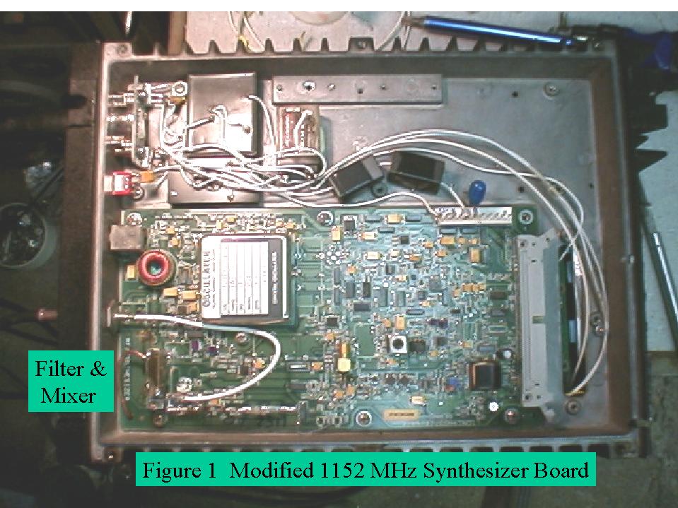
1152 MHz synthesizer board modifications:
An article available on the SBMS
website titled "1152 MHZ Surplus Qualcomm
RF/Synthesizer Board Conversion
Notes by N6IZW, K. Banke 12/1/97 , updated by Ed
Munn, W6OYJ" describes
the basic conversion procedure for modifying the board to
provide a stable, phase
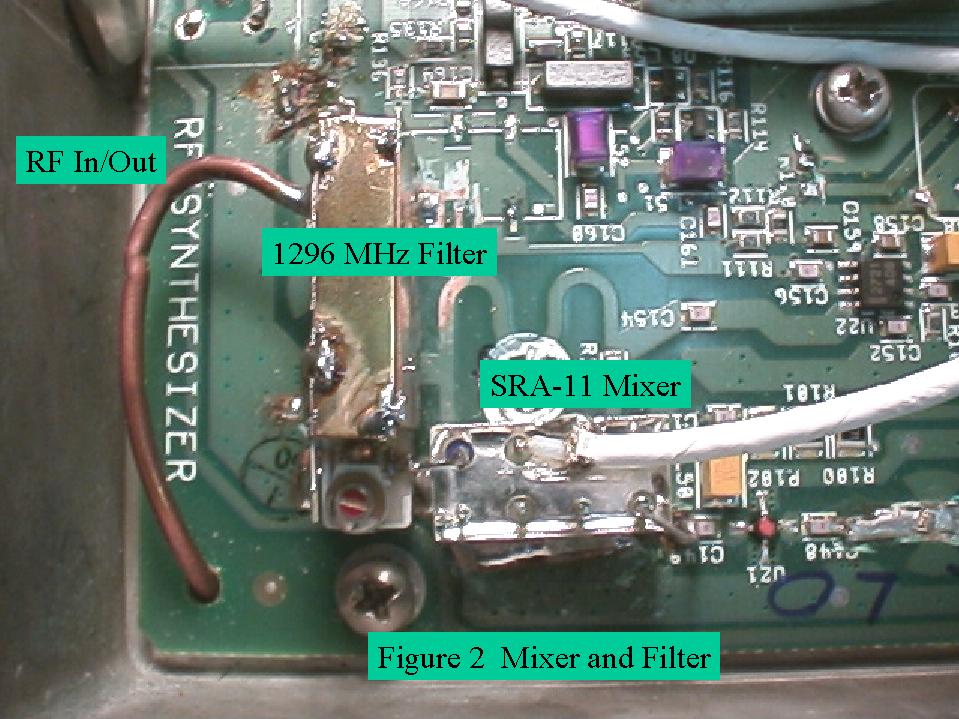
locked 1152 MHs LO. Figure 1 shows the overall 1152
board
as modified. Figure 2 shows the SRA-11 mixer mounted directly
to this
board as well as the ceramic 1296 MHz filter. If another filter is used,
an SMA
connector or small coax can be run from the RF port of the mixer to the
filter
which can be mounted on the opposite side of the chassis.
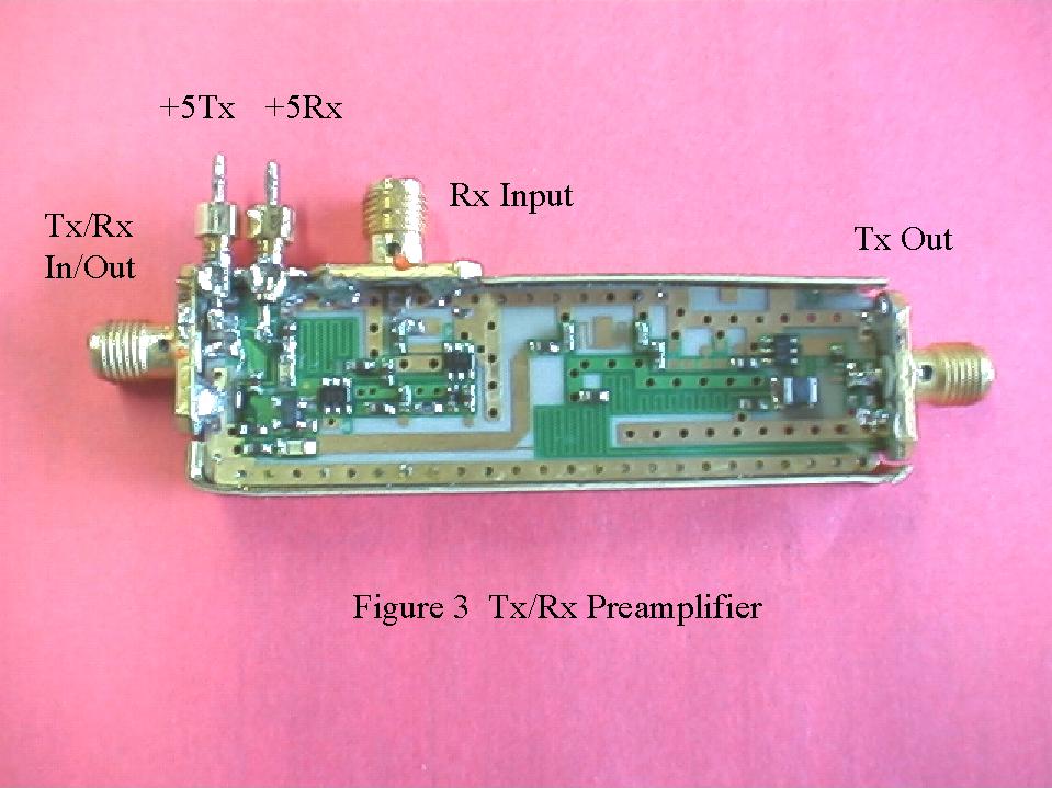
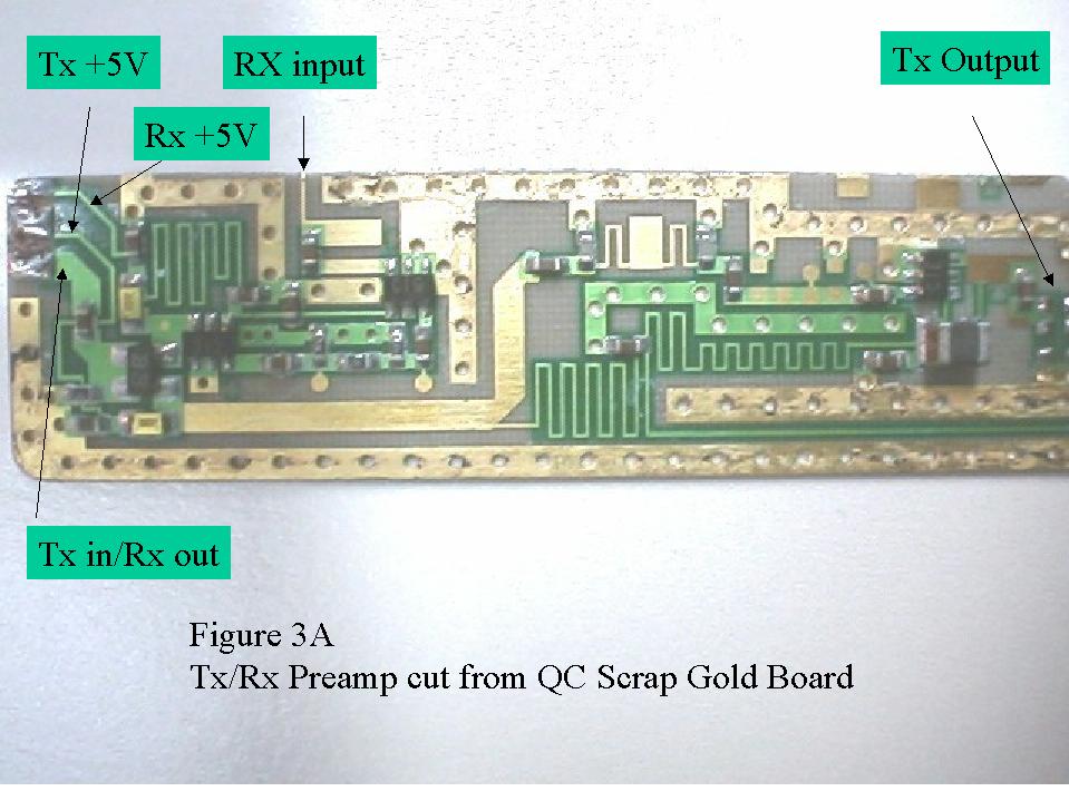
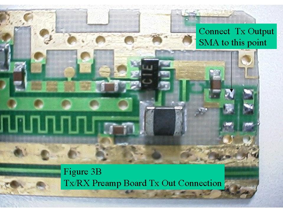
Tx/Rx preamp board modifications:
The Tx/RX preamp is cut from an earlier "QC
Gold Board" which was used to
convert to a 10 GHz xverter. This particular
version is useful as it has a
splitter/combiner which ties the Tx preamp input
and Rx preamp outputs to a
comon connection which is then fed directly to the
1296 MHz filter. Figures 3,
3a & 3b
show how SMA connectors are soldered onto the board along with the brass
shim
stock which serves as an enclosure. The Tx &Rx +5v supplies are connected
using
feed through capacitors.
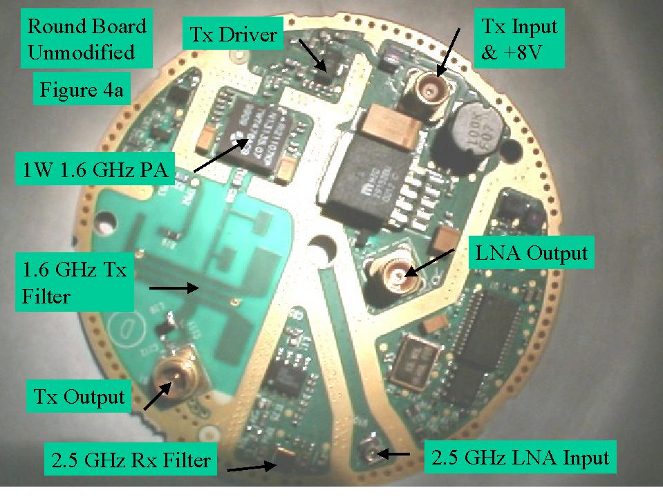
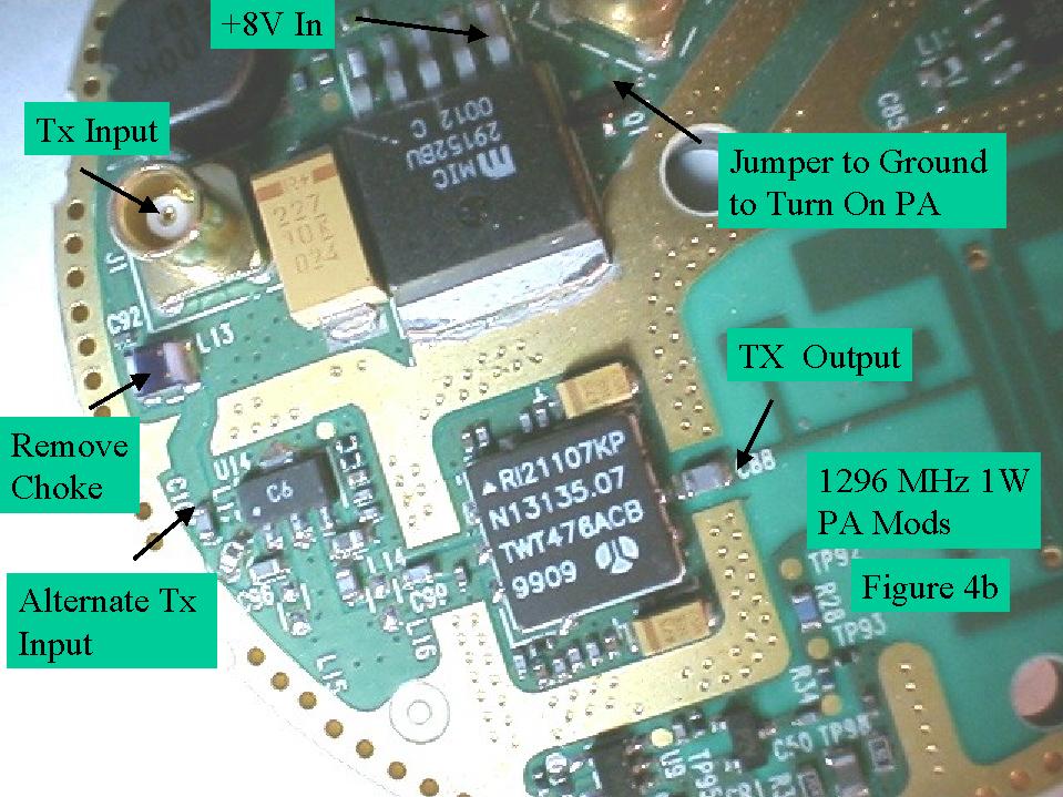
1 Watt PA: These units are modified "Round Boards" as shown in figures
4a and
4b. The input voltage required is 7-8 volts.
5+Watt PA:
The 5+watt PA.is currently in limited supply and hopefully more
will be
available in the future. These units are a section of board cut from
Globalstar
Fixed Phones which transmit around 1616 MHz. The retuning modifications
consist
of lifting off the metal cover and paralleling 3 capacitors. The module
must
be well heat sunk by screwing it to the xverter chassis. This PA requires
+ 9V
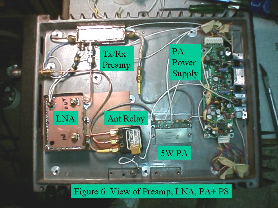
@ 2.5A , +7V @1.5A, and -4V. Figure 6 shows the bottom
side of the chassis with
Tx/Rx preamp, LNA, PA & such. The overall block
diagram of figure 7 shows how
the power supply normally used
for the QC 1 watt Ku band PA can be connected to
supply the required voltages.
The Pa is rated for +39 dBm out with +7 and +9
Volt supplies. At this time they
have been run at +7V for both supplies using
an LM317 regulator to drop the power
supply +9V to 7V. This provides about +37
dBm output maximum.
*****