

President Dick Bremer WB6DNX 1664 Holley St Brea CA 92621, 714-529-2800, rabremer@sbcglobal.net
VP Chris Shoaff N9RIN 2911 Calle Heraldo San Clemente CA 92673, 949-388-3121, cshoaff@netzero.net
Recording Sec Mel Swanberg, WA6JBD 231 E Alessandro Blvd Riverside, CA 92508, 909-369-6515, swanberg@pe.net
Corresponding Sec Kurt Geitner, K6RRA1077 E Pacific Coast Hwy #142 Seal Beach, CA 90740, 310-718-4910, k6rra@gte.net
Treasurer Dick Kolbly, K6HIJ 26335 Community Barstow, CA 92311, 760-253-2477, rkolbly@compuserve.com
Editor Bill Burns, WA6QYR 247 Rebel Rd Ridgecrest, CA 93555, 760-375-8566, bburns@ridgecrest.ca.us
Webmaster Chip Angle, N6CA 25309 Andreo Lomita, CA 90717, 310-539-5395, chip@anglelinear.com
ARRL Interface Frank Kelly, WB6CWN 1111 Rancho Conejo Blvd. #501 Newbury Park, CA 91320, 805-499-8047, fk@event1.com
W6IFE License Trustee Ed Munn, W6OYJ 6255 Radcliffe Dr. San Diego, CA 92122, 858-453-4563, edmunn@compuserve.com
At the 1 May 2003 meeting of the SBMS Wayne, KH6WZ will present a low loss polarity protection circuit with parts available. The SBMS meets at the American Legion Hall 1024 Main Street (south of the 91 freeway) in Corona, CA at 1900 hours local time on the first Thursday of each month. Check out the SBMS web site at http://www.ham-radio.com/sbms/.
Elections: Elected last meeting were- President, Dick, WB6DNX; Vice President, Chris, N9RIN; Treasurer, Dick K6HIJ; Corresponding Secretary Kurt, K6RRA; Recording Secretary Mel WA6JBD; Newsletter Editor Bill, WA6QYR
Last meeting Tony KC6QHC presented a slide show of his design and construction of his 24 GHz rig with motorized positioner. Good job Tony! Doug, K6JEY presented a video of the NASA Deep Space Tracking Station in Tidbinbilla, Australia. Thanks Doug. New members are Jerry Mulchin, N7EME of Coto de Caza CA; Greg Bailey, K6QPV of La Mesa; and Tony Long, KC6QHP of Redondo Beach. Welcome. Visitors were Howard Boger, WA6YGB and Gary, N7EB. Welcome. Ken WB6DTA had the last 24 GHz Pcom kit for the power switching for $10. Ken has more of the previous kits available for those building the Pcoms. Several people still need to get their @ GHz and up contest logs to Mike, W6YLZ@Juno.com. There was discussion on moving the 2 GHz contest later in the year for weather reasons. Tony KC6QHP was inducted into the SBMS GAB group.
Scheduling:
5 June Feeding of TWT's
14-16 June June VHF QSO Party
28-29 June Field Day
2-3 Aug UHF contest
16-17 Aug 10 GHz and Up contest
13-15 Sep VHF QSO Party
20-21 Sep 10 GHZ and Up contest second half
"Wants and Gots" for sale
Want HP715 Power Supply, X13 Klystron, and HP 809 and 810 unit- Ed K6ODV 909-689-1339.
Want ceramic caps 0.005 ufd @ 4kv Mike W6YLZ 881-349-8525
Want 10 GHz antenna and feed Wayne KH6WZ 714-846-1230 kh6wz@arrl.net
I'm looking for two standard flange WR-90 E plane bends and two short (<1")
flanged straight sections. Frank WB6CWN (805)230-2253
Activity reported at the April SBMS meeting- Doug, K6JEY went to Will, W6OEM qth and picked up some 75 GHz hardware, several people (N6IZW, WA6IGP, WA6NIA) are planning on getting on that band; Dick, WB6DNX worked on his 24 GHz LO and did some more machining; Chuck, WA6EXV worked the 2 GHz contest and has a Brooks Shera GPS reference working; Frank, WB6CWN visited Mr. Wizard (WA6EXV) qth, is building his 4th 10 GHz radio (one for self and one for friend) and is retuning an ebay amplifier; Bill WA6QYR was out on the 2 GHz contest, has been working on 60 KHz comparator, and has a new tower going up; Ed, W6OYJ participated in the 2 GHz contest, helped IZW on 24 GHz documentation and made some changes to the San Diego web site info; Kerry, N6IZW worked on documenting Pcom. The high side Pcom is easy to convert. LO feed through is a problem but Kerry had a fix. Kerry is using the original power supply. Ken, WB6DTA worked the 2 GHz contest, and had the last power control kit for the Pcom; Pat N6RMJ had fun on the 2 GHz contest, is collecting parts for a TWT, and has a new tripod; Dennis, WA6NIA was in the 2 GHz contest; Mike, W6YLZ was in the 2 GHz contest and has 15 SBMS logs but needs the rest, and did some Pcom work; Glenn, KE6HPZ was in the contest; Ed, K6ODV has a 12w 10 GHz amp and his 1296 antennas are ready go up again; Howard, WA6YGB has a home made dish on 1296; Wayne, KH6WZ has a DN6BT rig and has 7w amp on 3 GHz; Chris, N9RIN has an SSB rig in work; Tony, KC6QHP had a 2.3 GHz filter and divider to show; Dick, K6HIJ made a mold for WA6EXV sub reflector, is planning a trip to Moscow and has worked on a 24 GHz insertion loss meter to measure the waveguide switches he is building; Jerry N7EME is getting ready for the June contest with rigs from 6 meters to 1296 MHz; Larry, K6HLH worked the 2 GHz contest; Gary W6KVC has 90 ft of helical WR90 with connectors to boost his signals; Mel, WA6JBD is converting a satellite LNA to 10 GHz.
Email &endash; a good antenna discussion- (bill wa6qyr)
Dear Microwavers, Two rather good articles on the subject of RF Biohazard were published this month. .
The IEEE members who are members of the Microwave Theory and Techniques (MTT) Society will notice that the March 2003 issue of "Microwave Magazine" has two articles on the possible RF Biohazard risk of cell phones.
THE FIRST -- is a 4-page article entitled, "Risk to Children from Cellular Telephone Radiation" by James C. Lin of the University of Illinois.
............
THE SECOND -- is 2 page article entitled, "Cell Phones and Cancer: Anatomy of a Legal Opinion, by Rajeev Bansal of the University of Connecticut.
.............
THE FIRST -- article states that the cell phone market penetration is 80% or higher in many parts of Asia and Europe, but only 50% in the U.S. This is causing many companies to gawk at the U.S. market, especially its youth. Many Japanese youth own I-mode-enabled phones which let them get movie
information or find the latest "hot spot." But, only a small percentage of the U.S. youth own their own phone -- they use their parent's phones. These companies are about to offer third-generation hardware that is cheap and chic, with inexpensive service plans, to the U.S. youth. .............
However, marketing cell phones to youngsters is controversial. Some concerned parents and some authorities have asked the question, "is there a risk to children from cell phone radiation?" Opinions vary from, "there's no biological reason to think that children are any more at risk than
adults" to "there are gaps in knowledge about cell-phone safety." The British Minister for Public Health has published "The Stewart Report" which has urged that children be discouraged from using mobile phones, and that companies stop marketing to kids. Since then, several panels from other countries have recommended that children limit their use of mobile phones, but a few have stated that children need not be treated differently than adults. ...............
In response to a U.S. TV network report that was critical of the cell phone industry for marketing phones to children, the Walt Disney Company has stopped licensing its cartoon characters for cellular telephones until there is "reliable scientific evidence establishing the absence of risk."
.............
There are basically two concerns; (1) the spectacular growth and development changes of children's organs makes them more vulnerable to extrinsically caused diseases; and (2) the smaller size of their cranium
(compared to an adult) causes a different distribution of the RF Specific Absorption Rate (SAR). The article states that much research has occurred in this area during the last decade, and that research has been greatly helped by the existence of the finite-difference time-domain (FDTD) algorithm for analyzing complex biological bodies with internal details.
.............
However, two major laboratories -- one in Salt lake City, Utah, and one in Zurich, Switzerland -- have published well-documented reports that differ considerably, despite the use of very similar biological models and very similar computer algorithms. The differences in the laboratory reports may have caused some readers of the reports to loose faith in the validity of the results. The author of the MTT article studied the reports and concludes that the major difference is caused by the variation in the spacing between the cell phone antenna and the subject's head. Thus, it is possible that each report is valid. ..............
The MTT article does not give a clear conclusion that children should not be allowed to use mobile phones, it simply implies that there are greater risk factors for children. Since head size and growth rate are recognized factors, one could easily conclude that a much younger child (such as a 5 year old) is at greater risk. .........
I was disappointed that the time factor was not mentioned in the article, since it takes a time duration of exposure (like 6 minutes) to cause organ heating. I'm left with the question, should we not even allow a 5-year-old child to briefly speak to his mother over a mobile phone? .................
THE SECOND -- article describes the 800 million dollar law suit that Dr. Christopher Newman and his wife have filed against Motorola, two wireless industry associates, and several wireless service providers. Dr. Newman claims that the use of the 850 MHz analog cell phone caused his brain cancer. He is represented by a prominent Baltimore law firm that has successfully sued asbestos companies. .............
Early in 2002, the U.S. District Court for the District of Maryland directed both parties to begin the "discovery" phase, focused on the issues of both general and specific causation -- (1) can the use of a wireless handheld telephone cause brain cancer, and (2) did the use of the Motorola phone cause Dr. Newman's cancer. ............
A preliminary evidentiary hearing was held in February and March 2002, and post-hearing correspondence was received by the judge through September 2002. Later that month, Judge Catherine Blake dismissed the lawsuit. Her detailed memorandum provides useful insight on the legal admissibility of the Federal Rules of scientific evidence. She cited Daubert v. Merril Dow (1993) and asked these questions: ..........
o Whether a theory or technique can be or has been tested. .......
o Whether it has been subjected to peer review and publication. .......
o Whether a technique has a high known or potential rate of error and whether there are standards controlling its operation. ............
o Whether the theory or technique enjoys general acceptance within a relevant scientific community. ............
Judge Blake concluded that the causation opinions (cell phone usage causes brain cancer) did not pass the Daubert test. She felt the reasoning theories have not gained general acceptance in the scientific community, as demonstrated by the numerous national and international scientific published reports, finding no sufficient proof that the use of handheld cellular phones causes human brain cancer. The only published peer-reviewed epidemiological study finding such causation has serious flaws, and reliable epidemiology is essential before any link between animal studies and human cancer causation can be made. Neither Dr. Hardell's [Swedish epidemiological] work nor Dr. Lai's animal studies have been replicated or otherwise validated by other scientists. Further, Dr. Lai's published studies [performed at 2.45 GHz] lack relevance, or "fit," when applied to RFR or cell phone frequency [around 850 MHz for analog
phones]." ... "A court may conclude that there is simply too great an analytical gap between the data and the opinion proffered." .............
73 es Good VHF/UHF/SHF/EHF DX, .............Dick, K2RIW ...............Grid: FN30HT84DC27. .........
To: The Microwave Group
From: Dick, K2RIW 04/14/03
Re: WA5VJB's Antenna Article in May 2003 Scientific American. On page 88-89 of the Scientific American (Sci Am) May, 2003 issue contributing editor Mark Fischetti used quit a bit of the WA5VJB antenna explanation material from Kent's Radio Shack book "Antennas", by Alvis Evans and Kent Britain (1998) in a Sci Am article entitled "Antennas, Catch the Wave". Kent is also the editor of "Feed Point" the journal of the North Texas Microwave Society. The article has some nice illustrations that demonstrate a number of the antenna principles concerning a Ferrite Loop, Dipole, Yagi, Offset-Fed Parabolic Dish, Rabbit Ear, and a compacted Antenna-Amplifier (AntennaFire). The radio spectrum for AM Radio, Lower VHF TV, FM Radio, Upper VHF TV, Cell Phone, 802.11B, and DBS is illustrated with a horizontal Bar Graph. However, Mr. Fischetti allowed two minor errors to creep into the article:
(1) The 854 MHz Cell phone band requires a mono pole antenna of about 3.2" length (not 1.5"), and the wavelength is about 13" (not 3").
(2) An 18" Offset-Fed Parabolic Dish DSS antenna probably has an aperture efficiency of 65 to 70% (not 80%). An 80% efficiency would require near-perfect phase illumination, and an amplitude taper of about 5 dB, with no substantial spill-over energy. An ordinary Chaparral (or Scalar) feed horn is not capable of that kind of dish illumination performances. Over all, it's a rather nice article.
Hi Dick: Defending myself a little bit. I hardly had editorial control over the article, but helped clean up a few dozen errors in Mark's first draft. He never claimed the 3-inch antenna was 1/4 wave. Just an observation about what usually sticks out of cell phones. 80% efficiency for an offset dish is optimistic, and I've certainly never attained that myself, but Jasik in his book quotes Mittra and Cha of reporting efficiencies in the "80 to 90 percent range" Antenna Engineering Handbook 2nd Edition page 36-9 73's WA5VJB
TO: The Microwave Gang
From: Dick, K2RIW
RE: Can 80 to 90% Dish Efficiency be Achieved? -- Yes, and No (it better be big).
INTRODUCTION -- In his 4/15/03 submittal, Kent, WA5VJB quoted the Johnson & Jasik "Antenna Engineering Handbook", 2nd edition, 1984, page 36-9 as saying that the reference #16 article authors (Galindo-Israel, Mittra and Cha) are claiming that, "Their analytical techniques are reported to result in efficiencies in the 80 to 90 percent range". Kent is accurately quoting the Handbook, but there is a problem -- I believe the quote is being taken out of context. I'll supply 3 pieces of evidence of this, and I'll provide
a further discussion of possible Dish Efficiencies.
(1) Chapter 36 of the Handbook is devoted to "Earth Station Antennas" that are 60 to 300 wavelengths in diameter. As you are about to find out, some great "efficiency magic" is possible when you have a lot of wavelengths to play with.
(2) The type of antennas being discussed on page 36-9 are Double-offset Geometry dish antennas. This means that the feed horn is offset from the hyperbolic-like sub reflector, and the sub reflector is offset from the parabolic-like main reflector. These are rather complicated geometries that our Microwaver's may not be able to use, for some time to come (explained below).
(3) The "Analytical Techniques" being discussed are computer-modeled theoretical dish antennas that are using a Cassegrainian-like geometry that employs a "shaped" reflector and sub reflector. This means that the main reflector is an intentionally distorted parabola, and the sub reflector is an intentionally distorted hyperbola. The intentional distortions are being used to simultaneously improve the "Illumination Taper" while still providing essentially no unintended "Phase Taper" The computer-modeling techniques had to use "Diffraction Optimization" techniques for which there is no exact Geometric Optics (GO) solution -- whew!
MAXIMUM DISH EFFICIENCY -- I wish we had access to 90% aperture efficient Dish Antennas, and Horn Antennas. We usually do not, and you will soon see why. "Aperture Efficiency" and Sidelobe Levels are often misunderstood, and the detriment they cause is often misquoted. I hope the following material will help.
IT'S ALL IN THE FEED SYSTEM -- The requirements for high efficiency are easy to state, but quite hard to achieve. So, what's required for 100% efficiency -- no Phase Error (no phase taper), and no Amplitude Taper. If my great new "wizz-bang" feed horn system could provide exactly the same number of watts per square cm across my parabolic reflector, no spill-over energy at the edges, and no phase errors, than I'd have what's called a 100% Aperture Efficient dish antenna system.
TRANSMISSION & RECEPTION -- During transmit, almost every possible watt emitted by the antenna would be directed toward the target, and during reception, almost every "possible bit" of the signal hitting the antenna (from the correct direction and polarization) would be absorbed and sent down the feed line -- and it would often peg the S meter. If I had such an antenna, there would be no way that I could improve the transmission or reception, without increasing the size of the antenna.
SIDE LOBES & SCATTERING -- However, newly-instructed antenna engineers are usually quite surprised to find that a theoretical 100% Aperture Efficient (round dish) antenna will still have 1st side lobes that are about 17.5 dB down, and on reception the antenna still has a considerable "Scattering Area" that will show up on a good Instrumentation Radar.
SIDE LOBE ORIGIN -- The sidelobes are the result of the Diffraction Effect, caused by the abrupt fall-off of signal at the edge of the antenna. Simplistically, you could say that Mother Nature doesn't like a sharp discontinuity, and she responds by creating those pesky side lobes (they're almost always there).
SCATTERING ORIGIN -- A Free Space vacuum has an "impedance" of 120*Pi (377 ohms). The 100% Aperture Efficient, highly directional, dish antenna, will absorb the maximum signal if it also presents a matched impedance of 377 ohms. However, now there is a 377-ohm antenna across (in parallel with) the free space impedance of 377 ohms. The new local impedance is now 377/2 = 188.5 ohms. A free-space planar wave entering the vicinity of the antenna will "sense" the change in impedance, and a portion of the wave will become scattered at the impedance discontinuity.
MAKE IT DISAPPEAR -- There are ways to make the antenna sidelobes as low as you like, and there are ways to lower the Scattering Area as much as you please. But, all of these techniques must be accompanied by an Aperture Efficiency that is considerably lowered -- you can't have it both ways.
IT'S ALL IN THE SIZE OF IT -- I can almost achieve that nearly ideal Illumination Taper (0.0 dB) and Phase Taper (0.0 degrees). However, to have that much control over the radiation characteristics (primary pattern) of the Feed will require the horn to be made from a very large number of radiating elements that have a carefully-controlled amplitude and phase at each element. Such a "Cluster Feed" would really be an elaborate Phase Array Antenna, and I don't think you can come close to achieving the desired primary pattern with less than 1,000 elements -- a feed with about 38 wavelengths of diameter (43 inches [1.1 meters] at 10 GHz).
SMALL CASSEGRAINS -- I'm always amused when I encounter an enthusiastic, new Microwaver who becomes enthralled with a small-dish Cassegrain antenna system. Quite often they end up with a sub reflector design of 1.5-inch diameter at 10 GHz, and they start to worry about the accuracy requirement
for the Hyperbolic shape. There is a tried-and-true rule of thumb among informed antenna engineers, "don't even consider a Cassegrain system unless the sub reflector is at least 10 wavelengths in diameter".
A 1.5-inch subreflector at 10 GHz (1.3 wavelengths) is essentially a "Point Source" (almost isotropic). If your eyes functioned at 10 GHz, and you looked at an illuminated 1.5-inch sub reflector, it would look like a fuzzy white dot to you, and you couldn't tell if it was concave, convex, or flat -- they would all look the same. It take a large number of wavelengths of object size before your "vision system" begins to resolve the details. The 2-inch diameter of the sub reflector on my 8-inch Celestron Cassegrain telescope is 100,000 wavelengths in diameter -- that's a real sub reflector that can easily control the pattern it reflects!
CONCLUSION -- Concerning those super Aperture Efficiencies we sometimes hear about, they are possible, but difficult to achieve. And, I doubt we will see many of these in our back yards, unless we are talking about elaborate antenna designs that are hundreds of wavelengths in main dish diameter.
73 es Good UHF/SHF/EHF DX, Dick, K2RIW. Grid: FN30HT84DC27. Web: http://consult-li.com/listings/Rknadle.. htm
nu8i wrote:
Dick, K2RIW enscribed: [a lot of really good info, which I've snipped]
SCATTERING ORIGIN -- A Free Space vacuum has an "impedance" of 120*Pi (377 ohms). The 100% Aperture Efficient, highly directional, dish antenna, will absorb the maximum signal if it also presents a matched impedance of 377 ohms. However, now there is a 377-ohm antenna across (in parallel with) the free space impedance of 377 ohms. The new local impedance is now 377/2 = 188.5 ohms. A free-space planar wave entering the vicinity of the antenna will "sense" the change in impedance, and a portion of the wave will become scattered at the impedance discontinuity. I don't understand this point, however. If the antenna is matched to the>free space value, in other words looks to the incoming wave like a 377 ohm entity, how is there a discontinuity? Surely it appears to be no different than the surrounding medium. The only practical difference is that the>energy entering its aperture gets transferred to the receiver, rather than passing on to whatever may be behind the antenna. I don't see why you would place the free space impedance in parallel to the antenna. 73 Alf NU8I Scottsdale AZ
Alf & all, this is a property of all antennas. Most people don't understand it- it does not seem to make sense. Simply put, the scattering aperture of every matched antenna is equal to the receiving aperture. This property is true of EVERY ANTENNA. This means that exactly as much power as is delivered to the load (receiver) is also scattered from the antenna. This is not true if the antenna is not matched to the receiving load - the scattering will get worse, but if matched, then if 1 microwatt gets into a perfectly matched receiver, and there are no antenna (ohmic) losses, then 1 microwatt also gets radiated by the antenna. The radiation pattern for the scattering can be very complicated - in very simple antennas, like dipoles, it is the same pattern as the antenna, but with horns and dishes it is not.
Seems like it does not make much sense - but (as usual) Dick is telling it like it is. He and I have had some interesting discussions on exactly this topic. It appears in one line in the ARRL Antenna Handbook, and takes up a portion of an early chapter in Kraus.
This does not limit the antenna efficiency in any way. The antenna receiving (and therefore by reciprocity, the transmitting) aperture are identical, and are separate from, and in the perfectly matched case, equal to the scattering aperture. Intuitively, there is a "halo" around the dish so that there is additional aperture beyond the effective antenna aperture being affected. A dish will generate currents on its surface and along its rim, and the feed-horn will do the same, and radiate (scatter) as much energy as is being delivered to the receiver.
On another topic:
If a dish (as pointed out) were illuminated with even illumination amplitude and perfect phase center (not actually equal phase across the surface) and has no ohmic losses, it still would not have 100% efficiency. This is because of something called the "creeping wave" caused by currents induced in the dish. A portion of the energy comes off the back of the dish! Also, such an even illumination produces very high sidelobes, usually only about 13.5 dB below the main beam. A tapered illumination amplitude produces much lower sidelobes, and still can achieve efficiencies of over 50%. Some of the very best professional dish systems achieve about 80% efficiency without seriously large sidelobes.
What is even more important to me, is that being a wise guy and realizing that it takes many thousands of dollars for professionals to design and build dish feeds that achieve aperture efficiencies over 60 %, I made a wager with Paul Wade W1GHZ that he could not achieve over 60% efficiency with his own feed for the difficult to illuminate offset-fed dish. Of course, he won. Please consult Paul's on-line antenna book for all the really practical information and recipes for feeding dishes. It's a heck of a lot easier than the hairy math and poor results that you can get trying to start from basics!!!
Tom WA1MBA
The record for the 120 GHz band has changed hands several times already this year. Accepting the challenge by Brian, WA1ZMS, and his team, Bob, KF6KVG and I went over our rigs. Bob managed to tweak some more power out of his xmtr, and I found that one of my harmonic mixers was the best xmtr I have for 120 GHz. I modify these by removing the back short and installing an adaptor to take a x4 multiplier with 40.000 GHz output, about +15 dbm. The receive mixer is driven the same way at 39.900 GHz, all locked to 10 MHz.
Friday, Mar. 29 was a clear day with low humidity, so Bob went to the west side of the Santa Clara valley at CM87WJ. I was on the east side at CM97CJ, about 1000 ft elevation. Distance apart was about 24.8 km. We located each other by flashing mirrors, and had signals in about 10 minutes. The S-meter did not move, but CW copy was easy.
After exchanging info, Bob immediately moved to another location about 30 km apart. I was able to detect him, but he could not hear me. All in all, a successful day. Will
Hi all,
How do you say this?... but again....we took the efforts of Will, W0EOM and Bob KF6KVG with their latest world record of 24.6km as a challenge to try and better our East Coast efforts on 120GHz.
At the same time Will & Bob were doing 24km on the band, I was working in the shack trying an active bias circuit to improve my RX mixers at 120GHz.
The results were that W4WWQ, WA4RTS and myself took to the local hills of the Blue Ridge Mountains yet again and managed a few more QSOs on 120GHz with our best DX being 30.0km.
Date: April 2, 2003 Time: 05:18z <--- it was a late night. WA1ZMS/4 37-31-19.3 79-30-14.4 FM07fm
W4WWQ 37-21-09.7 79-14-20.3 FM07ji Distance 30.056km
WX on WA1ZMS end: Temp 10.5C Dew Point 0.5C Pressure 876mb RH 50% Loss 1.246dB/km
WX on W4WWQ end: Temp 16.7C Dew Point -0.6C Pressure 988mb RH 31% Loss 1.241dB/km
Another interesting point to note is that as Will and I each take our turns at bettering the other's DX, the
oxygen losses will become the limiting factor in all of our efforts. While the loss due to water vapor on this band may be around .24dB/km, the loss due to oxygen is around 1dB/km. So for someone to improve a DX record of say 30km by another 10km, they will need an improvement of 14.89dB!! (2.49 for free-space loss, 2.4dB for water loss, and 10dB for oxygen loss) The above values assume a typical semi-dry atmosphere. We'll need real QRO power for DX over 60km.
So...when Will takes the record back by a km or two (and he may already have) it might seem like splitting hairs but the loss per km from oxygen is a major obstacle to overcome and the efforts are not trivial.
I hope to have photos and an audio file of the latest QSO at http://www.mgef.org/ zms_120.htm over the next few days. 73, Brian, WA1ZMS.
----------------------------------------------------------
Microwave Update 2003 "White Papers" Sought
White papers are currently being solicited from potential authors and speakers for publication in the Microwave Update 2003 conference proceedings. Topics specifically of interest to Microwave Update 2003 attendees, as well as those on VHF and UHF subjects usually associated with the annual Pacific Northwest VHF Conference are solicited. Papers will be accepted until July 1, 2003. White papers should be sent directly to Jim Christiansen, K7ND, via e-mail at k7nd@att.net. MS Word format is preferred.
If you are interested in making a session presentation at one of the Microwave Update 2003 sessions, please respond to NU7Z (nu7z@aol.com); for presentations at the Pacific Northwest VHF Conference sessions, contact N7CFO (n7cfo@ix.Netcom.com). LCD projection equipment will be available for those using PowerPoint presentations (which are strongly encouraged). Slides and video presentations can also be accommodated with advance notice.
Microwave Update 2003 and the Pacific Northwest VHF Society respectively will be the sole judges of whether presentation requests and white papers are accepted.
Jim Aguirre
MUD 2003/Pacific Northwest VHF Society
Any one looking for sources of GPS receivers-
Hello Bill,
We currently have Trimble SK8's, DSM 8's and 12's and Marconi AllStar 12's. All of these receivers output a 1 pps signal. We have links to documentation for most of these receivers. Depending on quantity desired the price is flexible. For one or two our best price is $15.00 each.
Regards, -Greg
The shipping for the two receivers will be $7.50 (Priority Mail). If you would like, you can pay using PayPal (which we prefer) which will expedite your shipment. Our PayPal account is squint7769@hotmail.com. The total will be $37.50. If you wish to send a check please send to the following address.
Greg Donohoe
2633 S. Country Club Way
Tempe, AZ 85282
JAYHEY@aol.com
Best Regards, -Greg
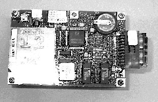
above: The Marconi AllStar 12 GPS receiver that Chuck WA6EXV has. This is a new project to have a field controlled frequency locked reference.
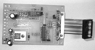
above: This is Chuck's adapter board to allow the AllStar to be connected to a computer or relock board.
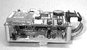
above: This is the package that Chuck, WA6EXV has with the AllStar and adapter boards assembled together.
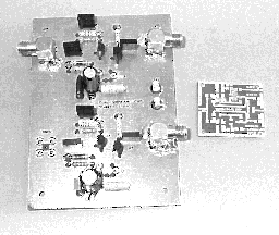
above: This is WA6EXV's 10 MHz distribution amplifier for isolating a signal source from a load or running the 10 MHz signal around the shack. Photos by WA6EXV.
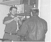
above:Tony KC6QHP being installed in to the GAB at the last SBMS meeting by the Wizard (K6JEY).
73's Bill
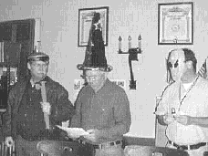
above: The Wizard and gang (K6JEY, WB6DNX, WA6JBD) at the last SBMS meeting getting ready to install an newbie.
The San Bernardino Microwave Society is a technical amateur radio club affiliated with the ARRL having a membership of over 90 amateurs from Hawaii and Alaska to the east coast and beyond. Dues are $15 per year, which includes a badge and monthly newsletter. Your mail label indicates your call followed by when your dues are due. Dues can be sent to the treasurer as listed under the banner on the front page. If you have material you would like in the newsletter please send it to Bill WA6QYR at 247 Rebel Road Ridgecrest, CA 93555, bburns@ridgecrest.ca.us, or phone 760-375-8566. The newsletter is generated about the 15th of the month and put into the mail at least the week prior to the meeting. This is your newsletter. SBMS Newsletter material can be copied as long as SBMS is identified as source.
San Bernardino Microwave Society newsletter
247 Rebel Road
Ridgecrest, CA
93555
USA