President Doug Millar, K6JEY 2791 Cedar Ave Long Beach, CA 90806 562-424-3737 dougnhelen@moonlink.net
VP Dave Glawson, WA6CGR 23437 E Amberwick Pl Diamond Bar CA 91765 909-861-7036 wa6cgr@ham-radio.com
Recording Sec Mel Swanberg, WA6JBD 231 E Alessandro Blvd Riverside, CA 92508 909-369-6515 swanberg@pe.net
Corresponding Sec Kurt Geitner, K6RRA 1077 E Pacific Coast Highway #142 Seal Beach, CA 90740 310-710-7810 k6rra@gte.net
Treasurer Dick Kolbly, K6HIJ 26335 Community Barstow, CA 92311 760-253-2477 rkolbly@compuserve.com
Editor Bill Burns, WA6QYR 247 Rebel Rd Ridgecrest, CA 93555 760-375-8566 bburns@ridgecrest.ca.us
Webmaster Chip Angle, N6CA 25309 Andreo Lomita, CA 90717 310-539-5395 chip@anglelinear.com
ARRL Interface Frank Kelly, WB6CWN 1111 Rancho Conejo Blvd. #501 Newbury Park, CA 91320 805-499-8047 fk@event1.com
W6IFE License Trustee Ed Munn, W6OYJ 6255 Radcliffe Dr. San Diego, CA 92122 619-453-4563 edmunn@compuserve.com
At the 6 March 2003 meeting of the SBMS Chuck, WA6EXV will talk about the construction and operation of the 1296 MHz to 2304 MHz translator and beacon which was installed on Heaps Peak, DM14kf in November. Nominations will be asked for from the floor prior to the April election of officers for the 2003-4 period. The SBMS meets at the American Legion Hall 1024 Main Street (south of the 91 freeway) in Corona, CA at 1900 hours local time on the first Thursday of each month. Check out the SBMS web site at http://www.ham-radio.com/sbms/.
Last meeting had Doug, K6JEY talk about the HP-Z3801A GPS receiver and its various revisions along with the software to allow you to control it. Doug had a handout on the various software available to work with GPS machines. Thanks Doug. Welcome to visitor Howard Bogen, WA6YGB of Pasadena and to Bill Davis, K0AWU of Grand Rapids, MN. Welcome to new members Bill Honeyman, KG6CNL of Huntington Beach; Steve Unger, AD6XQ of San Diego; and Wayne Yoshida, KH6WZ of Huntington Beach. Welcome. Chuck Swedblom, WA6EXV was presented with a Life Time Achievement Award from SBMS for his outstanding work in creating new technology applications for microwave use. Ken, WB6DTA had power supply kits for the 24 GHz Pcom rigs available. The 2 GHz and up contest was discussed. Reports from the ARRL 10 GHz contest were discussed as found on the ARRL web site and in QST. It was nice that a large number of SBMS members reported their activity from the contest. Chip, N6CA brought us the sad news that Gary Belda, K6ENS had passed away. It was reported that the Clint, W1LP ship had been sold to another group and had been scraped. 32 people present.
Pres Sez- Congratulations to those in the 10 GHz and Up contest. The number of log entries was fantastic. I suspect plans are in the works for better scores next year. I've been following with interest the developments on the millimeter wave and up bands done by hams in this and other parts of the country. Kerry, N6IZW and Chuck, WB6IGP have been working on coherent light communicators for several years now. Over time their experiments have produced slow and steady progress.
I'm sure others have had dreams about making equipment for higher bands but felt frustrated by either equipment or cost. I have some suggestions based upon what I have seen others do. First is to find a partner that will be someone to talk to and help with equipment or construction. Then pick a band or work your way up in frequency. We have stable high power sources at 12 and 24 GHz that are good building blocks for the higher bands. Form an alliance with other s. Use of specialized test equipment can be arranged by companies if you ask or know someone. You can sometimes borrow key pieces of equipment until you get your own. In some cases companies have donated components. It takes commitment and progress. When others see you are serious and capable, they will help. Just wishing or engineering will not do it. You have to get in and start building. Network with other hams that work on the same bands for advice. So any takers? What is your favorite band? 75 GHz or 144 GHz? Do you dare to go where no one has gone before? Doug K6JEY
Scheduling:
4 Apr K6JEY, Deep space Tracking Station in Tidbinbilla video. 2003-4 Elections.
1 May Feeding of TWT's
5 June TBD
"Wants and Gots" for sale
Want HP715 Power Supply, X13 Klystron, and HP 809 and 810 unit- Ed K6ODV 909-689-1339.
Want ceramic caps 0.005 uf @ 4kv (5kpf@4kv) Mike W6YLZ 881-349-8525
Want HP432A manual Ken WB6DTA 818-848-9059
Want HP8660 2.6 GHz RF plug-in and Siemens RW2135 TWT tube Frank WB6CWN 805-300-2902
Want- I am looking for two manually operated four port WR-90 waveguide transfer switches, or two waveguide transfer switches with bad motors/coils that can be removed, leaving the machined switch pieces. I could probably use switches that are non-functioning, jammed, or have impractical coil voltages, as long as they come apart. Frank WB6CWN 805-300-2902
Activity reported at the February SBMS meeting- Mel, WA6JBD worked on a 10 MHz standard frequency distribution amplifier for his shop; Rick, W6ESS has a 2 cm transverter; John, N6AX rebuilt his 24 GHz rig; Dick, WB6DNX did some machine work on aluminum blocks; Chuck, WA6EXV is working on a GPS frequency lock devise for locking his 10 GHz EME rig and is working on converting his 10 ft dish to a casagrain feed; Bill, WA6QYR brought in his 2 GHz helix he plans on using with a dish for AO-40 work; Frank, WB6CWN has a new 10 GHz rig and reworked an older Qualcomm front-end to have a 1 dB NF and 35 dB gain; Ken, WB6DTA has been working on Pcom documentation; Chuck, W7VX has been involved in some 432 MHz work; Ed, W6OYJ has 12w on 1296 MHz and did some 24 GHz rig work and put some new items on the San Diego Web site; Joonho, KG6MQS is working on a synthesizer; Steve, AD6XQ is working on a Qualcomm 10 GHz rig; Chris, N9RIN has his Qualcomm rig die and built a DN6NT rig; David, KI6FF had some parts to give away; Pat, N6RMJ has a 10 MHz battery powered oscillator for portable operation; Howard, , WA6YGB is working on a stressed parabolic dish; Ed, K6ODV is rebuilding his 1296 MHz loop yagi antenna after being blown down in the wind; Jeff, KN6VR is house building; Chip, N6CA indicated that the PV beacon is down and a new site is in the mill; Dick, K6HIJ is working on the construction of the wooden block for WA6EXV's sub-reflector; Paul, KH6HME is still visiting the mainland; Bill, K0AWU is a Central States club member and a Microwave Update attender; Gary, W6KVC working on 10 GHz ATV; Mike, W6YLZ is working on 24 GHz hardware; Dave, WA6CGR worked on network stuff; Doug, K6JEY working with schools on ham gear.
Items off the web--
Breaking the 3456 MHz North American DX record one km at a time.
On February 2, 2003 a high-pressure area set up over the Gulf of Mexico. As a result, we had some spectacular tropo from Texas to Florida with conditions also being good to Alabama, Georgia and Tennessee. My best microwave DX in the morning was to W4ZRZ in EM63 in Alabama on 1296 MHz. Later that evening, I decided to place a telephone call to Ron, WA8TTM/4 who resides in EL98DP. Ron had sent me numerous emails updating me on his 10 GHz efforts. At nearly midnight I get his voicemail which was probably better than getting one's wife at that hour. WA8TTM showed up on 2 meters some time later. WW2R and I proceeded to work Ron on 222, 432, 902, 1296, 2304 and even 3456 MHz. The distance from EM13QC to EL98DP is 1508 km based on the 6 digit grid squares. So, when I worked WA8TTM on 3456 MHz, I broke my old 3456 MHz record of 1507 km to KQ4PI. When WW2R tail-ended me and worked WA8TTM, Dave broke my record by one km extending the North American 3456 MHz record to 1509 km! A part of me said I just gave away my 3456 MHz record! But oh well.... records are made to be broken. I have had my share. We had no success on 10 GHz. My equipment on 3456 MHz is a 5 ft dish and 240 watts output. WW2R was running 5 watts output. I guess my 240 watts was warming up the atmosphere! Best Regards Al, W5LUA EM13QC Allen, Texas
47 GHz record bump. On Monday, Feb. 9 Bob, KF6KVG, and I made a contact on 47 GHz extending our previous best of 176 km to 246 km. Bob was east of Fresno near Grants Grove (DM06MS) and I was east of San Jose on Mt. Hamilton (CM97EI). We first acquired on 10 GHz as an aid in pointing (my compass was not working). We then went to 47 GHz and acquired in short order, about noon. Signals peaked at 20 db out of the noise with rapid fades up to 10 db. Equipment was the same as last year except I added a one-watt amp. It was really not needed for the contact but aided in acquiring. Information was exchanged by slow-speed cw. Weather was great, about 60 degrees, no wind, and low humidity. Monday was the last day of about a week of this weather. We had tried this path last summer without success. We did not try 76 GHz as we had converted those rigs to 144 GHz. Last Friday, Feb 7. We extended our range on that band to 25 km. Likely our best but a long ways from what the East coast crew did. Will W0EOM
Here is some back-up information on an item that was presented at our last meeting by Ed Munn.
---------------------------------------------------------
Gentleman:
On my recent trip to SoCal, there was some discussion of a 10GHz beacon re-installation possibility on Mt. Potosi. There was a beacon there for 1.5-2 yrs, about 8 yrs ago. At that time, the beacon transmitter, under 100mW & wide band mode, fed an antenna on the roof of a one-story bldg. with waveguide. The ant. was a small dish, not over 24-inch dia. It was pointed somewhere over towards Blue Ridge in the San Gabriel Mountains. There was uncertainty about the frequency. The local sponsor wasn't sure if anyone other than some hilltop portables had heard the signal in SoCal. There was speculation that it may have been heard on the Palos Verde's Peninsula. The local sponsor said that he used a wideband mode rcvr connected to a small dish to confirm continued reception of the signal locally, off the back of the antenna. There were times during these receiving periods that the signal was undetectable on the 30 plus mile path to Las Vegas.
To further this, I contacted a local ham that has extensive interests on Mt. Potosi. He can provide 2 rack units (2 X 1.75 inches), Rohn 25 tower space & 12VDC with a maximum primary demand of 120W. He indicated that antennas should be able to stand 100 MPH wind loading & about 1 inch of ice loading under infrequent condx. There may be other requirements, but I understand that this would be no ongoing cost to the beacon providers, but all of the equipment for the beacon and ant. System would have to be furnished. It would probably require a trip to/from Mt. Potosi for installation & a meeting with the local sponsor. Perhaps the actual site would have to be analyzed for affectivity. There are several of us locally in addition to the local sponsor who could be trained in the necessary procedures in case of problems. A means of detecting the signal here in Las Vegas would probably be necessary for periodic monitoring. The I.D. on the beacon would be that of the local sponsor per his request. The possibility of other frequency beacons may be possible, but 1296 & 2304 won't be welcomed because of other equipment on those bands on site.
These are mainly amateur ATV applications. A suggestion that an Omni antenna be used might be OK for local use, but not suitable for the relatively long distance to SoCal. Also, the previous installation used a limited run of flexible waveguide, which had enough loss as to make the under 100mW output levels compromised somewhat. After looking over the portable setups in SoCal, it was obvious that the xmtr to ant. Connection had to be very short, with the TX unit mtd right on the antenna. A 2W brick incorporated in the beacon package might be necessary for coverage. The low Potosi site is 32 mi. L.O.S. from my house, located in S.W. Las Vegas. In this matter, I am only a facilitator to the point of helping make this happen if the will is there. Pass the word if there is interest. 73, Al Olcott--K7ICW (702) 897-8410 k7icw@arrl.net
-----------------------------------------------------------------
RF Hazards by K2RIW. 19 Feb 2003 "Richard T. Knadle" <rknadle@suffolk.lib.ny.us>
Dear High Power Microwavers,
INTRODUCTION -- The high power Radars of the Marshal Island experience of Dave, K4TO, and the Trinidad experience of Jim, W4RX are good for illuminating many of the principles of RF Bio-hazard Assessment. Dave's situation is calculated here, and I suspect the conclusions could be equally applied to Jim's situation (repeated below). The aircraft that flew in front of Jim's radar were probably also at a safe distance. High Power Microwave (HPM) energy is something to treat with a healthy respect. When in doubt, please err on the side of being conservative. However, the subject is often misunderstood, and many people respond in a way that is more emotional than factual. As you will see, the most dangerous conditions that are possible are quite different from those you would consider by using "good common sense".
CALCULATION METHOD -- You will notice that calculations are performed in a step-by-step signal flow manner, so that the RF principles are illuminated. To many readers this methodology improves the memorization, and it increases the understanding, compared to simply plugging in numbers to a large equation with many variables.
K4TO's SITUATION -- Dave, K4TO gave us a "war story" (repeated below) concerning his experience in the Marshal Islands with one of the world's highest powered Radar systems. The 10 and 20 Megawatt Radars that fed a 150-foot dish sound like very dangerous pieces of hardware. As you will see by the following calculation, they probably were quite safe, particularly considering the way in which they were being used.
NON-IONIZING RADIATION -- The wavelengths that are far longer (lower in frequency) than the optical wavelengths are often called "non-ionizing". This means that the smallest unit of transmission (a photon) at this wavelength doesn't have enough energy to disrupt the molecules of your DNA. Thus, their only documented effect seems to be RF heating.
REFERENCE STANDARDS -- Arguably, one of the most authoritative documents on this subject is the ANSI IEEE C95.1-1991 Standard, published by the US American National Standards Institute. It has the title "IEEE Standard for Safety Levels with Respect to Human Exposure to RF Electromagnetic Fields, 3 kHz to 300 GHz". This document contains 450 references from many of the world's best research institutes, and it describes the compendium of opinions on this subject that have been gathered over the last 50 years. The RSGB uses a similar document that is recommended for the UK by the National Radiological Protection Board (NRPB).
MPEs -- The latest version of these documents describes the Maximum Permissible Exposure (MPE) levels that are allowed at various frequencies. It is interesting to note that the most stringent MPE is for the VHF frequency region of about 30 to 300 MHz. In this frequency region human tissue absorbs a majority of the RF energy that impinges on it, and converts it into heat. The most vulnerable organs are the eyes (possible cataract genesis) and the reproductive organs (possible temporary or permanent sterility), due to the fact that these organs have a low heat tolerance, and a restricted ability to dissipate excessive heat.
OTHER FREQUENCIES -- At lower RF frequencies a majority of the RF energy passes through human tissue and is not absorbed. At higher RF frequencies a majority of the RF energy is reflected at the skin surface. The so-called Microwave region above 1,500 MHz has an MPE that is 5 times higher than the 30 to 300 MHz region. To repeat, Microwaves are pound-for-pound 5 times safer than VHF frequencies.
SAFER MICROWAVES -- Although this is well documented, try to convince your local Zoning Board of this fact, and they are likely to think your are crazy. In the last 10 years I have given testimony before 12 Zoning Boards while defending amateur radio towers on Long Island, New York. The task is very challenging.
THE ALTAIR RADAR -- Dave's (K4TO) Marshal Island "Altair" Radar had a peak pulse power of 10 MW (at 155 MHz) and 20 MW (at 422 MHZ). Believe it or not, the most dangerous condition would occur if that RF power was radiated directly by the transmission line to that Radar dish. If the 422 MHz wave guide flange was simply "open circuited" to the air, that would constitute an "antenna" that has about 6 dB of gain and a VSWR of about 1.4:1. A person standing near that open circuited WG flange could absorb the average power of the RF transmitter (that hits him) and is converted into heat. If the vulnerable organs experienced a significant rise in temperature, than possible damage could occur.
THE DUTY FACTOR -- I'm assuming that the Altair Radar was a Long Range Search Radar, or an Over-the Horizon Radar. It is likely that the Radar had a pulse duty factor of 0.25% (0.0025) or less. Thus, the average transmitted power was probably about 50 kW. The ANSI C-95 specification says that the most stringent MPE for a "controlled environment" in the VHF frequency region is 1.0 milliwatt per square centimeter, averaged over a 6-minute period (360 seconds). The standard assumes that the vulnerable organs have a thermal time constant of 6 minutes.
SAFE DISTANCE -- Let's calculate how close you would have to stand to that open-ended WG flange to experience that MPE. This is done by assuming that the signal source radiates isotopic ally on the inside of a uniform sphere, and we must calculate how big a sphere is required for the Power Flux Density (PFD) to go down to 1.0 mW/(square cm). Remember that 1.0 mW/(sq. cm) equals 10 watts/(square meter).
The transmitter's 50 kW average with a WG flange gain of 6 dB equals an Effective Isotropic Radiated power (EIRP) of 200 kW average. A sphere that has an area of 200,000/10 = 20,000 square meters would be just right. The sphere's area is equal to 4*Pi*R^2 = 20,000 m^2. Solving for R equals 39.9 meters (131 feet). Therefore, a safe distance to the opened WG flange is 131 feet.
THE COMPLETE RADAR -- When the Altair Radar is operating, the feed horn tries to evenly distribute the 50 kW of average power over the surface of the 150-foot dish. That would give the dish the maximum possible gain of 46.1 dBi at 422 MHz. The best the horn can do is to create a 10 dB amplitude taper, which lowers the dish efficiency to about 60%, and the gain will be about 43.9 dBi (1.2 degrees of beamwidth).
THE PFD AT THE REFLECTOR -- The 150 foot dish has a projected surface area of 17,671 square feet (1,642 square meters), if it is a round dish. If the horn could evenly distribute the 50 kW of RF energy on the dish surface, that would equal a PFD of 30.5 watts/(square meter). Because of the amplitude taper and edge spillover the PFD at the center of the dish is probably about 4 times greater, or about 122 watts/(sq. meter). This PFD is 12.2 times the current MPE. Because the ANSI Standard has a 10:1 safety factor built into it, that might actually be almost a safe exposure level. In other words, you could lie at the center of the dish while the Radar is operating for 360/12.2 = 29.5 seconds, and be safe by the most stringent portion of the current ANSI standard.
COLLIMATION -- The parabolic surface of the dish takes the spherical wavefront from the feed horn and collimates it into a nearly parallel beam. As you stand at some distance in front of the dish, the spread of the energy will cause the PFD to drop below the 122 watts/(sq meter) level.
NEAR FIELD RANGE -- Let's see what happens if you stand at the best distance in front of the dish. A 150 foot dish at 422 MHz has a Near Field Range of 2^D^2/Lambda = 19,294 feet (3.65 miles or 5.9 km). At that distance (or greater) the dish achieves about the best performance of Gain and Pattern. 50 kW (average) into a dish with a gain of 43.9 dBi yields an EIRP of 1.23 GW, or 121 dBm (average power). At 3.65 miles at 422 MHz the Free Space Loss is equal to -100.3 dB. An Isotropic antenna in the boresight of that Radar at a distance of 3.65 miles would receive an average signal of 121 -100.3 = +20.7 dBm. An Isotropic antenna has an Effective Area of Lambda^2/(4*Pi) = 0.04 meter^2. Therefore an Isotropic signal of +20.7 dBm (117 mW) equals a PFD of 0.117/0.04 = 2.9 watts/(square meter). This is an MPE that is 3.4:1 below the current ANSI Standard of 10 watts/meter^2, and it is actually a safe PFD for continuous exposure.
DECREASING DISTANCE -- If you were at 3.65 miles in the boresight of the Altair Radar and you began walking toward the dish, the PFD would increase by less than 15 dB and peak at a distance of 1/5 the NFR, than it would decrease by 3 dB and continue to oscillate between two levels that are less than 3 dB apart. As you get closer two things happen: (1) the Free Space Loss decreases; (2) the apparent dish gain begins to decrease because portions of the reflecting surface becomes out-of-phase at your range. Experience with most dishes has shown that rarely does the PFD become more than 15 dB stronger than it is at the Near Field Range, and it almost never exceeds the PFD that exists at the apex of the dish reflector, unless the dish was intentionally made "nearsighted" by translating the horn beyond the normal focal distance.
The maximum PFD would occur at 1/5 of the NFR, or 0.73 miles. At that distance the 15 dB increase in PFD (from 2.9 Watts/meter^2) would be 92.4 watts/meter^2, which is below the estimated PFD at the apex of the dish reflector -- that was about 122 Watts/(sq meter). These worse case PFD's are very close to the old MPE, which didn't have the recently added 10:1 safety factor.
At a 1.0 mile range (0.27 of the NFR of 3.65 miles), where Jim's living quarters were, the calculated PFD will increase by 10.9 dB, and increase from 2.9 W/m^2 to 35.7 W/m^2. That's 3.6 times the current ANSI Standard, but considerably below the standard that existed at that time (100 W/m^2). Thus, it was prudent that his living quarters were RF shielded structures.
All of these calculations assume that the dish is continuously staring in a particular direction -- that's the worse case condition. If the dish was continuously rotating, then the Biohazard assessments become many times safer, as long as it doesn't dwell for 6 minutes in a particular direction that contains biological material.
CONCLUSIONS -- The surprise of a real-world Radar situation is that the RF Biohazard actually decreases when you use a higher gain dish antenna. This is because it distributes the transmitted energy over a large surface area, and the PFD always decreases from that point as the range is increased. A bird that lands on the feed horn while the Radar is operating will probably not survive for more than a couple of minutes. Birds like to do this when the dish is not rotating. Under these conditions Radar operators will sometimes find dead birds lying below a Radar dish.
A naive technologist will sometimes use the peak power of a Radar instead of the average power. Then they will simply add the antenna gain (in dB's) to the peak transmitter power (in dBm) to calculate the EIRP. This methodology can give results that are doubly pessimistic in assessing the near-by RF Safety. They failed to realize that RF primarily creates a heating effect, and the heating is proportional to the average power, not the peak power. Also, the full antenna gain is only realized in the Far Field. When you're up close, portions of the antenna are out of phase, and do not fully contribute to the resultant PFD.
I hope this material is helpful in increasing the understanding of RF Bio-hazards. Feel free to correct the math errors. 73 es Good VHF/UHF/SHF DX, Dick, K2RIW. Grid: FN30HT84DC27.
Web: http://consult-li.com/listings/Rknadle.htm
Good morning,
As long as we are swapping "war stories" I might as well put my hat in the ring. For five and a half years I worked In the Marshall Islands. Some of you may even have worked me as KX6DS. I was employed by the folks who ran the ALTAIR radar site. ALTAIR is a dual band VHF/UHF radar using a 150-foot dish. The transmitted power on VHF is 10 Megawatts and on UHF 20 Megawatts, peak. This is BEFORE it gets to the 150-foot dish. You make the calculations on ERP.
We had safety limit switches that would disable the transmitters below a certain elevation and within certain azimuth limits that pointed at the living quarters, which were a mile away. Also on the island was another radar called the millimeter wavelength radar. I don't know the power or frequency of that one, but before it was fired up, a truck with a red light and siren was sent all around the island (The island was about 1 mile in diameter.). Nobody was allowed outside while this radar was on. All of the building on the island were RF shielded. BTW, the ALTAIR frequencies were 155 and 422 MHz. I was the receiver engineer and my "receiver" consisted of 60 six-foot racks of electronics. There were eight feeds coming from the dish, LC, RC, Az, and El for each radar. All signal paths had to be phase matched to within less than a degree. I am trying to remember what sort of test equipment we used, but I believe my present bench setup with a 22 GHz spectrum analyzer and 18 GHz counter exceeds the capability that I had on the island :-) Thanks for allowing my to reminisce a bit. 73, Dave, K4TO
-----------------------------------------------------------------------------------------------
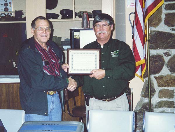
During the February SBMS meeting Chuck Swedblom, WA6EXV was presented a Life Time Achievement Award for his efforts to promote amateur radio microwave activity and technology. This is the text from that presentation.
Chuck was born in Montana on February 19, 1926. The family moved to Idaho when Chuck was 6 years old. They had a small ranch near McCall, Idaho. Chuck learned many tasks while ranching. His father ran a pack train for the U.S. Forest Service and did guide and pack trips for private hunting groups. Later Chuck would work as a Forest Guard putting in lookouts and running phone lines into the back country. He would also be a fire fighter when that was needed. Skiing was also part of Chuck's life in High School. Chuck joined the Navy and went through electronics and radio schools. He was stationed on Hawaii from 1943 to the end of the war, where he took care of transmitters for the pacific operations. He became a licensed amateur some time during 1943. His call was W7JHX.
He married Jean in 1946 and moved to Moscow, Idaho where he attended the University of Idaho, and later to Kansas, where he went to Central Radio & Television School, in Kansas City, MO. His call while in Kansas was W0OZH.
After returning to Idaho he worked for a Radio Supply Company in Boise. Having joined a Naval Reserve Unit while at the University of Idaho, he was active in a reserve unit in Boise. He was called to active duty during the Korean conflict and was stationed at the Tongue Point Naval Base in Astoria Oregon. Following discharge, he moved his family to Port Orchard, Washington where he managed a radio and TV service shop. During this time he played with HF and VHF radios and experimented with ATV over 10 GHz.
Chuck worked for Philco Corporation Technical Representative Division and was stationed at Edwards Air Force Base Rocket test site in the late 1950's. Since then his call sign has been WA6EXV. He was transferred to the Navy Lab at Corona California and was assigned to the naval base at China Lake in 1960. In 1966 he became an employee of the government at China Lake where he retired in 1987.
Chuck and Jean moved to Ridgecrest in the 1960's and eventually to their present location between Ridgecrest and Inyokern because it had better VHF path to Southern California and he could put up bigger antennas than in the city.
When Bill, WA6QYR moved to China Lake in 1969, he met Chuck. Chuck became a member of SBMS that Bill had joined a couple of years before. The two have been driving to monthly meetings ever since.
During the period from 1972 to 1974 Chuck was instrumental in designing a 2.3 GHz beacon to go on board Oscar 7. Working along with Chuck were Gordon Lowery, WA6ZKY, Dick Kolbly, K6HIJ and Frank Adams, W6BPK.
In 1973 Chuck took the five foot rack full of vacuum tubes ROCKLOC design and turned it into a Solid State ROCKLOC design when running transistors at several hundred volts was still a novel idea. Klystrons took little current but three hundred volts for the repeller and negative 600 volts for the cathode.
In 1977 Chuck built a ROCKLOC system with a solid state 10 GHz Gunnplexer instead of a klystron. This wideband fm XCVR design was published by Microwave Associates in an Application Note that appeared in May 1977. An updated version using the RCA CA-3089 fm if amplifier/detector is still published in the ARRL Handbook.
In the spring of 1978 Chuck had taken an old telemetry transmitter and converted into a beacon with ID'er and it was installed as the First 2.3 GHz Beacon on Heaps Peak.
Antennas were another area of interest to Chuck. He built his own antenna range in order to test his designs and projects of other amateurs.
Solid-state oscillators were coming on line in the late 1970's and by mid-80's they had grown in power capability. In 1987 Chuck designed and built two high-power 100-milliwatt Gunn 10 GHz sources. He gave one to Ed Munn W6OYJ who used it to take top score in the next ARRL 10 GHz Contest, outscoring Chuck by only 300 pts out of 10,500.
As technology progressed, so did Chuck's projects. In the 1990 time period a commercial surplus of Microwave Associates 12 GHz data transmission units became available through some surplus dealers. Chuck took some of the hardware and converted them to the amateur 10 GHz band use and provided documentation to the amateur microwave community.
Over the years, Chuck has produced several excellent LNA designs for 10 GHz.
Also in the 1990 time period Chuck designed and built a Kilowatt Transmitter for 13 cm EME using a Microwave Oven Magnetron. His excellent article was published in the Jan 1991 Communications Quarterly Magazine. In May 1992 the first California 10 GHz EME QSO was from Chuck, WA6EXV Ridgecrest to Jim, WA7CJO in Phoenix.
In July 1993 Chuck and Phil Lee, W6HCC set the North American 10 GHz Terrestrial DX record from Mt Pinos to Mt Ashland Oregon; 537 miles/865 Km. This was the 2nd attempt over the long path.
Between 1991-93 Chuck and Phil teamed up to see how many grids they could work on 10 GHz from Heap's Peak, and later from Keller Peak. As of 1994 they reached 31 Grids for Chuck and 34 for Phil.
In 1994 Chuck and Phil made the first California-to-California 10 GHz EME QSO. This was from Chuck's QTH in Ridgecrest to Phil in Beaumont.
In Dave Laag, K6OW's outstanding 1994 article on SBMS History, he stated he wanted to choose one SBMS figure from the last 25 years who had had the most influence on local and general Amateur Microwave progress. Paraphrasing Dave's article---- Chuck Swedblom, WA6EXV brought the rest of us from the older technologies like klystrons..... to rapid deployment of newer technologies, first to Gunnplexers, then "Narrowband" and finally PHEMTs and the moon. Dave then repeated a statement made by Frank, WB6CWN, that efforts such as those by Chuck "allowed the rest of us to look great while standing on the shoulders of giants".
By 1996 Chuck had continued to push our boundaries by moving up to the 24 GHz band, first with Gunn wideband systems. That year the ARRL added "and UP" to the 10 GHz Contest, and Chuck finished in third place with a combined band score of over 12,000 points and best DX of 178 Km. on the higher band. He experimented with higher power Gunn sources but was unhappy with their drift problems. This drove him to work toward 24 GHz narrowband capability, including the need for decent LNAs and stable LOs. By 2000 he was operating with a "thoroughly modern", all homebrew 24 GHz rig and urging the rest of us to join him.
A major SBMS effort began in 2001 to replace the twenty year old 2.3 GHz Heap's Peak Beacon. Chuck, working with hardware from Sam K6VLM along with some of his own designs built the new 1.2 to 2.3 GHz beacon- translator and antennas that were installed in November of 2002. As part of this effort a main antenna goal was to have omnidirectional horizontal polarization with significant gain. Chuck discovered major problems with widely accepted Slot Antenna design formulas and software, produced an excellent antenna, and disseminated the results to other microwavers. This is a good example of the thoroughness he exhibits in every project, and in his desire to share his findings with others.
Chuck has been there for us, and has been pushing us to have better equipment and make longer distance contacts.
On behalf of the San Bernardino Microwave Society it is my privilege to present Chuck Swedblom with the Society's Lifetime Achievement Award.
73's Bill
Chuck Swedblom, WA6EXV (left) was presented the SBMS Life Time Achievement Award at the February meeting by President Doug Millar, K6JEY
The San Bernardino Microwave Society is a technical amateur radio club affiliated with the ARRL having a membership of over 90 amateurs from Hawaii and Alaska to the east coast and beyond. Dues are $15 per year, which includes a badge and monthly newsletter. Your mail label indicates your call followed by when your dues are due. Dues can be sent to the treasurer as listed under the banner on the front page. If you have material you would like in the newsletter please send it to Bill WA6QYR at 247 Rebel Road Ridgecrest, CA 93555, bburns@ridgecrest.ca.us, or phone 760-375-8566. The newsletter is generated about the 15th of the month and put into the mail at least the week prior to the meeting. This is your newsletter. SBMS Newsletter material can be copied as long as SBMS is identified as source.
San Bernardino Microwave Society newsletter
247 Rebel Road
Ridgecrest, CA
93555
USA