
President Dick Bremer WB6DNX 1664 Holley St Brea CA 92621, 714-529-2800, rabremer@sbcglobal.net
VP Chris Shoaff N9RIN 2911 Calle Heraldo San Clemente CA 92673, 949-388-3121, cshoaff@netzero.net
Recording Sec Mel Swanberg, WA6JBD 231 E Alessandro Blvd Riverside, CA 92508, 909-369-6515, swanberg@pe.net
Corresponding Sec Kurt Geitner, K6RRA1077 E Pacific Coast Hwy #142 Seal Beach, CA 90740, 310-718-4910, k6rra@gte.net
Treasurer Dick Kolbly, K6HIJ 26335 Community Barstow, CA 92311, 760-253-2477, rkolbly@compuserve.com
Editor Bill Burns, WA6QYR 247 Rebel Rd Ridgecrest, CA 93555, 760-375-8566, bburns@ridgecrest.ca.us
Webmaster Chip Angle, N6CA 25309 Andreo Lomita, CA 90717, 310-539-5395, chip@anglelinear.com
ARRL Interface Frank Kelly, WB6CWN 1111 Rancho Conejo Blvd. #501 Newbury Park, CA 91320, 805-499-8047, fk@event1.com
W6IFE License Trustee Ed Munn, W6OYJ 6255 Radcliffe Dr. San Diego, CA 92122, 858-453-4563, edmunn@compuserve.com
At the 5 June 2003 meeting of the SBMS someone will talk about feeding of TWT's. The SBMS meets at the American Legion Hall 1024 Main Street (south of the 91 freeway) in Corona, CA at 1900 hours local time on the first Thursday of each month. Check out the SBMS web site at http://www.ham-radio.com/sbms/.
Last meeting- Wayne, KH6WZ presented a nice talk on devises to prevent battery power from being connected backwards (wrong polarity). Good talk Wayne. Welcome to new members Robert Brown KR7O of Madera and Howard Bogen WB6YGB of Pasadena. Discussion of the 2 GHz and Up contest dates will be the topic of the next meeting. A number of Clubs around the US had weather problems in March and would like it moved to a time when the snow is gone. SBMS score had 11 contacts on 2.3 GHz; 12 contacts on 3 GHz; 90 contacts on 10 GHz and 2 contacts on 24 GHz. 21 people present at meeting.
Scheduling:
14-16 June VHF QSO Party
28-29 June Field Day
3 July TBD
2-3 Aug UHF contest
7 August TBD
16-17 Aug 10 GHz and Up contest
4 Sept TBD
13-15 Sep VHF QSO Party
20-21 Sep 10 GHZ and Up contest second half
"Wants and Gots" for sale
Want--Does anyone have a source for a small 3 to 4 inch dish that could be used on 47 GHz. Need small one for experimental use. Reply to clhough@pacbell.net Thanks Chuck WB6IGP
Want- WR90 waveguide- a 90 degree bend, 2-3 ft of flex, 2 wr90 quick disconnects, 24 GHz circulator; 26 GHz sma relay; 2 sma to WR42 Adapters Mike W6YLZ 818-349-8525 or 310-383-1000
Want wr42 flanges and straight waveguide Wayne KH6WZ 310-252-7726 KH6WZ@arrl.net.
Want 10 GHz dish and feed Bill KG6CNL 714-969-4724 bill@honeyman.com
Free- 6 ft rack on wheels Larry K6HLH ljohns@qnte.com
Activity reported at the 1 May SBMS meeting- Dick, WB6DNX did Pcom mixer board and filter LO, machined a new feed holder; Mel, WA6JBD getting the rigs ready for the summer; Chuck, WA6EXV worked on a 2 GHz 3 w amp using new devices, built a Qualcomm LNA using gold board parts with 35 dB gain 1.5 dB NF; Bill, WA6QYR received a county permit to put up new tower for local club repeater, did some work on the AllStar GPS board; Ed, W6OYJ documented the high side Pcom which is on web site now and started the low side Pcom documentation; Mike W6YLZ had TWT power supply problem and now has 20 w TWT working with the 4 ft offset dish mounted, did some work on the Pcom boards; Ken WB6DTA modified some DRO synthesizer boards and made more Pcom kits; Wayne, KH6WZ is now integrating his 10 GHz hardware; Bill KG6CNL has some DN6MT hardware and is looking for a dish; Rick, W6ESS did some 1.2 GHz work; Tony, KC6QHP has a counter TRW swap meet and did some PPL work; Pat, N6RJM rebuilt his 10 GHz rig on to a new tripod; Gary, w6kvc WORKED THE baker to Vegas race on ATV; Doug, K6JEY did some 76 GHz work; Jerry N7EME did some 222 MHz transmitter work and has a 1296 rig working; Howard WA6YGB did some power supply work; Larry, K6HLH made some 3 GHz contacts and rebuilt his 10 GHz rig on to a new tripod; Chris, N9RIN did some 3 ft dish work and DN6NT hardware work.
RESULTS OF THE 2003
2GHZ AND UP WORLD WIDE CLUB CONTEST
SPONSORED BY THE S.B.M.S.
SAN BERNARDINO MICROWAVE SOCIETY
CLUB ENTRIES SCORE ORIGINAL CORRECTED
SAN BERNADINO MICROWAVE SOCIETY 16 21,468 21,468
Mt Airy VHF CLUB "PACKRATS" 08 7,610 12,510
MIDWEST VHF UHF SOCIETY CLUB 04 4,498 6,316
SAN DIEGO MICROWAVE GROUP 04 8,108 6,108
These were the only logs I received; you will notice that the scores are different from what was submitted
This was a result of me not explaining the scoring process more clearly.
I have gone through the logs that were sent and corrected to best of what I can figure out I will explain as best I can again and rules will be rewritten better for next year. Each band is counted separately, Power level multipliers are separate for each band, Unique calls are separate for each band
Total distance in km X power level multiplier + unique calls for that band = band score
Total all bands to get total score
I hope this helps for next time, also we are looking at moving the date later in the year about a month, better
Weather and need to promote this, any suggestions are welcome, please respond ton6rjm@direcway.com
N6RMJ PAT DM14cp
K2RIW Discussion: Antenna Scattering Area, Part 2.
INTRODUCTION -- Portions of this memo will be controversial to some readers. The concepts that will be expressed constitute a "Model" that has been created for the purpose of predicting antenna reception characteristics, of both complex and simple antenna types. Although the Model may be flawed, it has done a good job of explaining the phenomena of Aperture Efficiency, and Scattering Area. There probably will be other Microwave Reflector memos that question the concept, or express a different point of view -- I welcome these (within reason). When the smoke settles, I believe we will arrive at a higher understanding of antennas.
In Part 1 (4/23/03), I discussed the Scattering Area and the Reciprocal characteristics of a Dipole antenna. The main point expressed is that there are TWO (2) types of impedance matching that effect the efficiency of the Reciprocity process:
(1) Electronic Impedance Matching -- That's what you do at the feed point of the antenna to insure that all the transmitter power is absorbed by the antenna (from the feed line).
(2) Spacial Impedance Matching (Spacial Pattern Matching)-- This addresses how well your Reception Testing Procedure matched the Transmission Characteristics of the antenna-under-test (AUT). Maybe it would be better to call this item Spacial Pattern Matching, or Aperture Distribution Matching; that might give it greater visibility to more readers. But, the bottom line is this: if the total pattern of the energy (signal strength versus azimuth, elevation, and polarimetry) that is presented to the antenna during a Reception Test does not match (by 100%) the COMPLETE pattern that the antenna presented during the Transmission Test, then the antenna will reject a portion of the energy intended for reception, and the magnitude of that rejection can be quantified as the antenna's Scattering Area.
ITEM (2) IS MAJOR -- Most antenna engineers seem to think that Item (1) is the one that causes the magnitude of the Scattering Area that an antenna displays. But, in most circumstances Item (2) has the greatest effect.
The concept within Item (2) seems to create the greatest grief among people studying antennas, so I'll elaborate it. There are two general characteristics by which an Electronically Impedance Matched antenna cannot accept the energy presented to it from space: Polarimetry Error, and Spacial Pattern Error.
POLARIMETRY ERROR -- If I was testing a horizontally polarized antenna and I sent vertically polarized energy toward the antenna during a reception test, few engineers would have any problem accepting the notion that the AUT (Antenna Under test) will have little response to that energy. For most low-mass types of antennas (such as Dipoles and Yagis) the antenna is rather transparent to the cross-polarized energy; that energy will pass through the region of the antenna with little disturbance to the energy. However, for more complex (or massive) types of antennas, such as a Horn or a Dish, the antenna will present a kind of "short circuit" to the cross-polarized energy, and that energy will be reflected, deflected, diffracted, and generally scattered. It will appear as the antenna's Scattering Area.
SPACIAL PATTERN EFFECT, BACK LOBE RESPONSE -- If I was testing a well-tuned Yagi antenna that had a good Front-to-Back ratio, and I was applying the co-polarized reception energy to the back of the antenna, obviously the antenna would have little response. However, in this case the antenna is not transparent to that energy. The Reflector, Driven Element, and nearby Directors are responding to that energy, but their tuning is such that they are presenting an Interferometry Null, are Phasing
Null at the Driven Element to the energy that arrives from that direction. A well-constructed Yagi has no lossy properties associated with it, so it cannot dissipate this energy. By the Law of Conservation of Energy, this energy must be scattered in some other direction, or it must be generally reflected back in the direction from where it came. I believe that the back of such a Yagi will present a Scattering Area that is at least twice as large as that of a normal Dipole antenna. Under ordinary conditions, a Dipole has a Scattering area that is equal to it's Effective Area, but the Dipole that is part of this Yagi's rearward reception has an Effective Area of near zero, therefore it's Scattering Area must at least double, because the Dipole and other elements involved.
SPACIAL PATTERN MATCHING, FRONT LOBE -- Many Standard Gain Horn antennas have a gain of about 16 dBi. The Amplitude Distribution across the mouth of the horn has a half SIN-wave-like distribution, with the emitted signal strongest in the center, and near zero at the vertical edges (vertical polarization is assumed). If I place a pair of identical horns together, mouth-to-mouth, the insertion loss between them will be nearly zero dB (no loss). This condition will persist, even if I create a space between the horns of quite a few wavelengths. This nearly 100% energy transfer between the horns suggests that during this test, each presents an Effective Area of nearly 100% to the other, and a Scattering Area of nearly zero.
NEAR FIELD COUPLING? -- There are antenna engineers who will simply dismiss this test by saying, "the horns are within the Near Field Range of each other, they were reactively coupled, therefore the 100% energy transfer (although accurate) is not relevant". I disagree. There are many situations where one portion of an antenna system is well within the Near Field Range of another portion, and the system performs admirably, and in a predictable manner. Here are a few examples:
(1) In every Parabolic Dish antenna system, the horn is way inside the Near Field Range of the main parabolic reflector.
(2) In every Cassegrain antenna system, the sub reflector is way inside the Near Field Range of the main parabolic reflector, and in most of the them the parabolic reflector (and the horn) are inside the Near Field Range of the hyperbolic sub-reflector.
(3) In many Periscope Antenna Systems, the 45-degree "flyswatter reflector" and the ground-mounted parabolic illuminator are inside the Near Field Range of each other.
(4) In every optical telescope, all of the individual lenses and mirrors are within the Near Field Range of the other elements, often by a 100,000 to 1 ratio.
(5) The two 45 degree mirrors that are within a child's optical periscope are within the Near Field Range of each other by a 60,000 to 1 ratio.
(6) At 10 GHz my 3 foot dish antenna has a calculated Near Field Range of 189 feet. Yet, I can aim a pair of identical dish antennas at each other with a separation of 3 feet, and the insertion loss between them will be nearly zero dB. Each antenna will act like a collimator to the other antenna, each will present the proper Aperture Distribution to the other, and the energy transfer between them will be nearly complete. In that test the apparent Scattering Area between the antennas will seem to be very small. However, in a Far Field reception test, the antenna will experience a uniform Aperture Distribution, and the Scattering Area will be much higher. Which is the real Scattering Area? It seems to be a function of Definition, or of the Testing Procedure (test conditions).
STANDARD GAIN HORN RECEPTION -- If I use one of the Standard Gain Horns in a reception test while receiving a planar wave that was emitted from a long distance, the Standard Gain Horn will have a reception efficiency (Aperture Efficiency) of about 60 to 70%. In other words, the Effective Area (~ 65%) will be larger than the Scattering Area (~ 35%). At first, this may seem to be a paradox. The horn has a radiating efficiency of nearly 100% when it is used for transmitting a signal, yet it has an Aperture Efficiency of about 65% during normal signal reception, and an Aperture Efficiency (Effective Area) of near 100% when receiving the signal from an identical nearby horn.
AMPLITUDE DISTRIBUTION MATCHING -- I say that the reason for this difference is the matching of the Aperture Distribution from the nearby horn (the half SIN-wave-like distribution), versus the mismatch of the far-field spacial signal (it presents a Uniform Distribution). At first, the Uniform Distribution created by the spacial wave sounds like the most desirable one for best reception. However, the horn is not "tuned" for that kind of Aperture Distribution, therefore it can not accept all of that type of spacial signal. The horn's half SIN-wave-like Aperture Distribution created a particular Antenna Pattern (Spacial Amplitude Pattern over the 4 Pi Steradians of space) when the horn was transmitting. Only when that same (and complete) Antenna Pattern is presented to the horn during a reception test will the horn experience the same half SIN-wave-like Aperture Distribution, and thus be able to accept 100% of the energy being presented to it -- which would be displayed as a 100% Aperture Efficiency. There is a one-to-one Reciprocal Relationship between an antenna's Aperture Distribution, and the Spacial Antenna Pattern it produces while transmitting.
RE-READ? -- I believe that many readers should re-read the last five paragraphs multiple times, in order to absorb the concept. To most technologists who are exposed to this concept for the first time, it sounds crazy. I know of no respected textbook that makes this concept clear. Among the antenna engineers who have had 20 to 30 years experience in the field, I believe that fewer than 20% of them understand this concept. Yet, it is a very important concept if one desires to understand the origin of
Dish Antenna Aperture Efficiency, or Stealth A/C RCS (Radar Cross Section). For instance, any attempt to create a Low Observable Aircraft (A/C) must entail a thorough understanding of the concept of Antenna Scattering Area. It would be a rather wasteful exercise to put forth a heroic effort to build a stealthy A/C, only to have it become a "Gang Buster" echo on a Radar screen because of the Scattering Area of the antennas that were installed on that A/C -- this has happened many times. There are solutions to this problem, but they are all very difficult to implement, and those solutions would not improve the performance of our amateur microwave antennas.
DISH ANTENNA APERTURE EFFICIENCY -- For most Parabolic Dish Antenna systems a "well-designed feed horn" will present a reflector edge illumination of -10 dB compared to the dish center. This Illumination Taper results in a dish Aperture Efficiency of about 55 to 65%. If it was possible to design an "ideal horn" that presented an Amplitude Taper of 0.0 dB across the reflector, with no wasted edge spillover energy, then the antenna system could have an Aperture Efficiency of nearly 100%.
60% APERTURE EFFICIENCY? -- Most Microwavers have trouble understanding where the 55 to 65% Aperture Efficiency comes from in a "real" dish antenna system. Often their flawed point of view is the following: "on reception the parabolic reflector brings all the energy to a focus at the center of the feed horn, therefore a good horn has no choice but to accept all that energy." Unfortunately, the horn will not accept all the energy, unless it is presented to the horn with exactly the correct three-dimensional amplitude pattern (primary horn pattern) that the horn was designed for.
DISH SPACIAL PATTERN MISS-MATCH -- During boresight reception of a far-off planar wave, the wave presents a Uniform Amplitude Distribution across the parabolic reflector. After reflection, the portion of the wave that hit the dish perimeter region will approach the horn with an almost equal amplitude as the portion of the wave that hit the center of the dish. That total reflected signal now has a nearly uniform signal strength versus angle as it is approaching the horn. The horn will not accept all the energy that has that pattern; it was designed to transmit (or receive) energy that has a -10 dB amplitude taper across the angles of the reflector. The portion of the signal that is not accepted by the horn will be reflected back (Scattered) to the parabolic reflector and re-transmitted back into space. This Spacial Pattern miss-match (and reflection [Scattering]) phenomenon is a three-dimensional characteristic of antennas that is quite difficult for many engineers to accept. Therefore, I'll present a pair of two-dimensional examples that may make it more clear.
HYBRID COMPARISON, Example (1) -- Assume that I'm using a Wilkinson Half Hybrid as a power divider. A 50 ohm Wilkinson is the Hybrid that has a pair of 1/4 wave 70 ohm lines connected from the common port to the two output ports, with an internal 100 ohm isolation load resistor between the two output ports. I'll first apply 2 watts to the common port (I'll call this the "transmission" test), and I'll notice that each of the two output ports will display a 1-watt signal, that has a zero degree phase difference between the outputs. To test the Reciprocity Characteristic, I'll next apply a pair of 1-watt co-phase signals to the two output ports (I'll call this the "reception" test), and I'll notice that the common port now has a 2-watt output. Notice that between "transmission" test and "reception" test I realized 100% efficiency and Reciprocity was demonstrated. However, if during the "reception" test I present a pair of signals that differ in relative amplitude (or phase), than the 100-ohm resistor will experience a differential signal, and signal dissipation will take place. You could say that the Hybrid rejected (or dissipated) the "reception" signals that did not exactly match the "transmission" conditions. You could say that the Wilkinson Hybrid has some similarity to a theoretical Zero dB Taper feed horn.
HYBRID COMPARISON, EXAMPLE (2) -- Assume that I'm using a well-designed coaxial-type -10 dB Directional Coupler as an unequal power divider -- it's somewhat like a -10 dB Taper Feed Horn. During the "transmission" test I'll apply a 10-watt signal to the Common port, and I'll realize a 9-watt signal (with a 90 degree lagging phase shift) at the Straight Through port, and a 1-watt signal (at zero degrees phase shift) at the Directional port. Notice that the efficiency is 100%. During the first "reception" test I'll completely reverse the process by applying a 1 watt signal to the Directional port, and a 9 watt signal (with a 90 degree leading phase angle) to the Straight Through port. At the Common port I'll measure a 10-watt signal (100% efficiency), and most of the Reciprocity process will be demonstrated. But, notice that the phase angle must be reversed during the Reception Test -- both Antennas, Hybrids, and Directional Couplers behave in this way. During the second "reception" test I'll apply only the 9-watt signal to the Straight Through output port, and no signal to the Directional port. At the Common port I'll measure 8.1 watts (a power loss of 10%, -0.46 dB). Now, the Directional Coupler seems to have gone down from 100% to 90% efficiency because I didn't properly match the "transmission" conditions. Due to the mismatch of the "transmission" conditions, the extra 0.9 watts (-0.46 dB) was lost in the internal 50-ohm termination. During the first "reception" test, the -0.46 dB of Directional Coupler straight through path insertion loss didn't take place; this can be viewed in at least two ways:
(1) If all the "transmission" conditions are preserved (with a phase reversal) then Reciprocity will be demonstrated.
(2) During the first "reception" test the Coupler's internal 50 ohm termination saw a 0.9 watt signal from the 9 watt source, and a 0.9 watt signal from the 1 watt source, but the two 0.9 watt signals were 180 degrees out of phase, thus the termination saw 0.0 volts and no dissipation of energy took place -- one of the benefits of matching the "transmission" conditions.
ANTENNA-HYBRID ANALOGY -- In both the Antenna and the Hybrid examples, power will be "wasted" if the "transmission" conditions (amplitudes at the Hybrid ports, or amplitudes at the various Antenna angles) are not 100% duplicated during a "reception" test. The only difference between them is where the "wasted" power goes. The "wasted" power becomes scattered in the case of an antenna Spacial Pattern Mismatch. In a Hybrid mismatched "reception" test the "wasted" power becomes dissipated in the Hybrid's internal termination. There have been some "simplified" Hybrids that do not have an internal termination (such as the 4:1 power divider that amateurs use to feed 4 antennas); these will scatter the mismatched "reception" power back to the antennas. Similarly the Hybrids in the previous examples would scatter the mismatched "reception" energy back to the sources, if their internal terminations were removed. Well-designed antennas have no lossy elements associated with them; therefore they Scatter (and do not dissipate) the Spacial Pattern Mismatched energy that is presented to them.
ANTENNA/HYBRID DIFFERENCES -- In the previous example a -10 dB Directional Coupler was being compared to a -10 dB Illumination Taper Feed Horn. When the -10 dB signal (the 1 watt signal) was omitted during the "reception" test, the Coupler's efficiency decreased from 100% to 90% (-0.46 dB).
However, in a Parabolic Dish Antenna, the -10 dB illuminated area at the dish perimeter has much more area that the 0.0 dB illuminated area near the center, thus it includes a substantial amount of the dish "transmitting" energy. This would be equivalent to using a Directional Coupler that had a number of -10 dB output ports (each with an internal 50 ohm termination). If the "reception" signals were omitted from all the -10 dB Coupler ports, the impact on the Coupler's efficiency would be a decrease to 60% (-2.2 dB); this would be similar to the dish Aperture Efficiency of 60% that occurs during the reception of the Far Field wave that has the "mismatched" Uniform Distribution signal that creates the Spacial Pattern Mismatch at the feed horn.
PRELIMINARY CONCLUSION -- The concept expressed within this memo may seem quite radical to many readers, and maybe the concept contains errors. However, over the years a good number of technically savvy people have come to accept the concept as being real. I have used the concept to explain the measurements that I and my colleagues have experienced while using an Instrumentation Radar to measure the Scattering Area of various antennas under various conditions. As stated earlier, the Model may be flawed, but it has (thus far) done an excellent job of explaining the observed measurements.
BORESIGHT ONLY -- Most of the main lobe Aperture Efficiencies and Scattering Areas that have been discussed only apply to the antenna's boresight response. Beginning at angles that are slightly off of boresight, some very different phenomena begins to happen; it's called Structural Scattering. These characteristics, and some Scattering Area surprises, will be discussed in a subsequent memo (next week).
73 es Good VHF/UHF/SHF DX, Dick, K2RIW Web: http://consult-li.com/listings/Rknadle.htm.
Hello Microwavers, Today we revised the SBMS Web page info on the Pcom 23 GHz High-
Side LO Mods for Amateur 24 GHz operation. In particular the description of the mods to the Pcom Synthesizer Module is expanded and hopefully clarified with new photos and labels. This new info does NOT apply directly to modification of the Synthesizer Module in the Low-Side LO versions of the Pcom ODU. We hope to publish modifications for the Low-Side LO ODU soon. You can access the new info at:
Http://www.ham-radio.com/sbms/sd/pc23mods.html. And then select the article on the Pcom High Side LO Modifications.73s from Ed Munn, W6OYJ 858-453-4563
Hello So. Calif. Microwavers, Some of you may hear a beacon signal on 10368.330 MHz during the next few weeks. This is a replacement for the Santiago Peak Beacon, however it is being "burned in" in a different location. Currently operating at the 10-mill watt level, it will soon have the power level raised to 1 watt. Please ignore the location and grid given by the cw identifier as Santiago Peak DM13FR. The actual location during this test period is in grid DM12MQ, southeast of San Diego: 32 deg 41.802 min N and 116 deg 56.094 min W. The call sign of the beacon is KE6JUV. We hope to have it reinstalled on Santiago Peak in the near future. Please send any reception reports to Greg Bailey, K6QPV. His email address is: gbailey@mail.sdsu.edu. 73s from Ed, W6OYJ
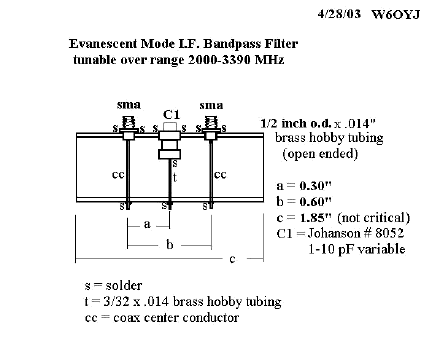
Hello Microwavers, I made a filter using 0.5 inch diameter hobby brass tubing operating in the evanescent waveguide mode. Easy to put together and solder, and tunes over the 2.0 to 3.3 GHz range. The design is adapted from the 1993 Microwave Update article by Reed Fisher W2CQH, which described the use of rectangular waveguide for these filters.
Insertion loss measured at under 2 dB at 3072 MHz
-3dB bandwidth 28 MHz
-10 dB bw = 90 MHz
-20 dB bw = 270 MHz
-25 dB bw = 470 MHz
-30 dB bw = 810 MHz and mostly flat beyond this
These filters would work for the Pcom i.f. filters at 2208 or 3072 MHz. Diagram attached is file"fltr3072a.jpg" This will be added to the SBMS web pages on the Pcom Mods. 73s from Ed, W6OYJ
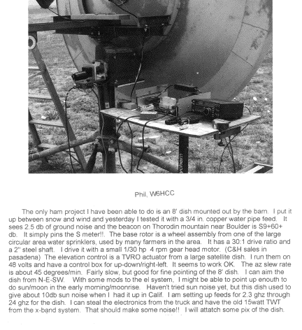
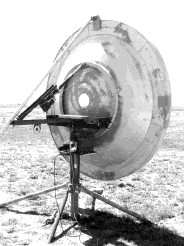
above: W6HCC dish
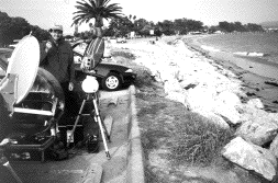
Above: Tony, KC6QHP at Gaviota Beach with the motorized 10 GHz dish pointer.
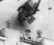
(above) SBMS member Dick Kolbly, K6HIJ was on a trip to Moscow and had a chance to visit a number of Russian hams and see what they do. Dick having worked at the US NASA deep space tracking station at Goldstone CA in the 60's and 70's thought it was a great treat to visit the Russian counterpart at Bear Lake. Here shown is Vladimir, RW3AAE (left), K6HIJ, and Sergei, RW3BP at one of the Bear's Lake tracking sites. This is a 15M dish used for tracking an Indian communications satellite on 150, 400, and 2300 MHz. (BearLake.jpg)
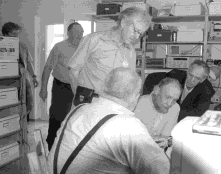
(above) The second picture is a group of hams at RW3BP shack (We were discussing the stabilization of oven magnetrons, which was a hot topic). Left to right: Alexy, son of RW3BP (call sign unknown), Vladmir, RW3AAE; Sergei, RW3BP; K6HIJ, Vladimir, RA3ACE (?), and Vladimir (call sign unknown). (HAM1GA.jpg)
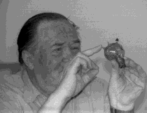
(above) This is the shack of RA3ACE, who does mostly building. On the table is a home-brew transceiver for VHF/UHF bands. He made his own circuit boards using a fly cutter. If you think US hams have the corner on lots of gear on the desktop, think again. Home built stuff&emdash;WOW!
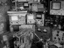
(above) This is the shack of RA3ACE, who does mostly building. On the table is a home-brew transceiver for VHF/UHF bands. He made his own circuit boards using a fly cutter. If you think US hams have the corner on lots of gear on the desktop, think again. Home built stuff&emdash;WOW!
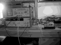
(above) This picture was taken in the shack of Sergei, RW3BP. We were using his 47 GHz scalar network analyzer to measure how well our (K6HIJ) homemade tuner would match a load (open ended waveguide, in this case.) And we think we have hard times getting gear to work the upper bands&emdash;just build your own test equipment too.

(above) Here is the last photo. It is of Vladmir, Sergei, and son in front of the 10-foot antenna that Sergei has mounted on the roof of his apartment building. He has successfully done EME up to 24GHz, and is now trying to get on 47GHz. Dick indicated that in Russia society is pushed in to communal type housing in apartment type buildings. Sergei and family were able to get on an upper floor of one of the buildings so he could have his ham gear mounted on the roof.
73, Dick
The San Bernardino Microwave Society is a technical amateur radio club affiliated with the ARRL having a membership of over 90 amateurs from Hawaii and Alaska to the east coast and beyond. Dues are $15 per year, which includes a badge and monthly newsletter. Your mail label indicates your call followed by when your dues are due. Dues can be sent to the treasurer as listed under the banner on the front page. If you have material you would like in the newsletter please send it to Bill WA6QYR at 247 Rebel Road Ridgecrest, CA 93555, bburns@ridgecrest.ca.us, or phone 760-375-8566. The newsletter is generated about the 15th of the month and put into the mail at least the week prior to the meeting. This is your newsletter. SBMS Newsletter material can be copied as long as SBMS is identified as source.
San Bernardino Microwave Society newsletter
247 Rebel Road
Ridgecrest, CA
93555
USA