1. The Project - The goal of this project is to modify P-Com 23 GHz Tel-Link Out Door Units (ODU's) to Amateur 24 GHz SSB transverters while maintaining the original case and antenna mounting configuration.
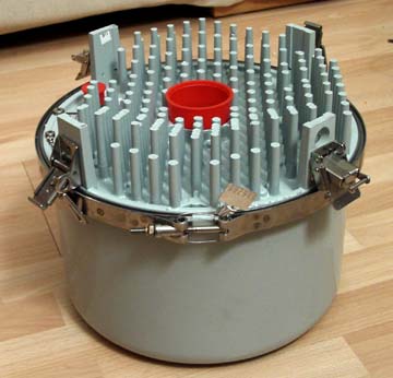
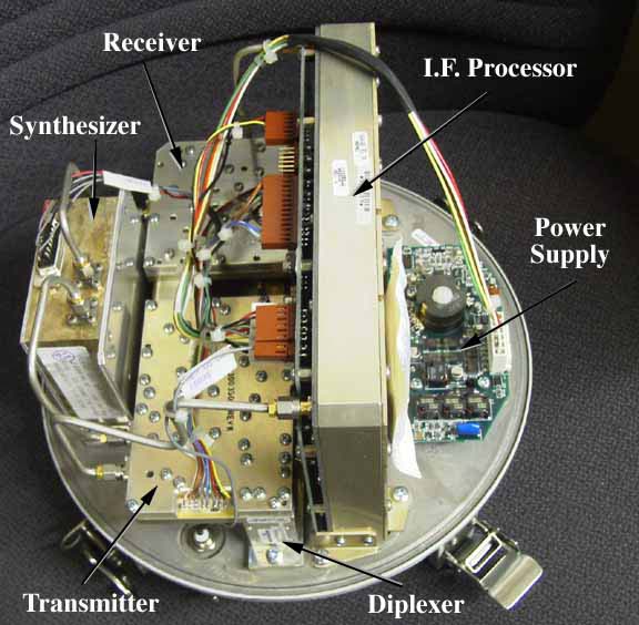
2. The ODU - The P-Com Out Door Unit consists of an IF Processor, a Power Supply which receives -48 volts from the IF Processor, a Synthesizer, a Receive Module, a Transmit Module (rated at either +16 dBm or +21 dBm at 23 GHz) and an antenna Diplexer. The P-Com ODU is approximately 12" in diameter and about 12" high. These particular units were manufactured by REMEC in San Diego, CA.
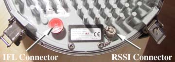
It has two coax connectors, a type 'N' connector which normally connects the ODU to any of a series of P-Com InDoor Units (IDU's) through up to 150' of 9913 50 Ohm coax. The IDU's generate a transmit IF of about 300 MHz, have a receive IF of 140 MHz and provide -48 volts to the ODU all through the 9913 coax. This coax cable is called an IFL or Inter Facility Link cable. The other coax connector on the ODU is a 'BNC' connector which serves as the 'RSSI' or Receive Signal Strength
Indicator (S-Meter) connector.
The antenna attaches to the ODU via 4 'latches' on the ODU. The ODU has an antenna 'port' which is a 3/8" circular waveguide port that mates to the antenna's circular waveguide connector. The (optional) matching 2 foot P-Com dish antennas contain the feed and radome and come with a mounting bracket that will mount to 2" to 4" pipes.
The power supply converts the -48 volts (referenced to the ODU chassis) to +12, +5 and -5 volts. The output of the power supply connects back to the IF processor module which provides a central connector bank that feeds all of the other modules.
The synthesizer modules have variations among the units we have seen (about 25) in that some are high side local oscillators in the 21 GHz units and low side local oscillators in the 23 GHz units. The low frequency units are in the range of 9.6 GHz and the high frequency units are in the 12 GHz range. The units are originally designed to operate in 84 channels spaced at 7 MHz between channels.
The transmit and receive modules use surface mount devices which allows for easier modification. The original high IF frequency in the first modified unit was 3,775 MHz and the original output frequency was in the range of 23.012 GHz transmit and 22.004 GHz receive. The L.O. frequency applied to the transmit and receive module is 1/2 the actual operational L.O. frequency. The L.O. frequency is doubled in the transmit and receive modules.
The diplexer has a transmit/receive split of 1 GHz with circular waveguide antenna port and WR-42 waveguide input and output for the transmit and receive modules. There is a circulator between the diplexer and the transmit module as well as between the diplexer and the receive module.
The transmit and receive modules have WR-42 antenna ports and SMA connectors for the L.O. and I.F. ports.
3. The Plan - The agreed upon frequency configuration is as follows:
a) The operating frequency is 24.192 GHz
b) The Amateur I.F. frequency is 432.000 MHz
c) The internal high I.F. frequency is 3.072 GHz
d) The L.O. frequency is 10.560 GHz
The high I.F. frequency of 3.072 GHz was chosen so as not to have to move the transmit and receive module filters too far (from 3.775 GHz).
4. Progress to Date 11/16/2001 - Synthesizers -
The synthesizers in their original form have several problems that needed to be resolved. Specifically:
a) The frequency stability of the synthesizer reference oscillator is rated at +/- 8 ppm! Not adequate for SSB use requiring less than 0.5 ppm. An external QualComm 10 MHz TCXO was chosen to replace the original TCXO.
b) There was significant digital noise generated by communication between the I.F. processor and the synthesizer (exchanging channel information). This communication was disabled.
c) The synthesizer loop filter is too slow causing slow lock-up and in-sufficient sideband supression. This has been resolved by changing the loop component values.
d) The synthesizer V.C.O. requires modification to increase the frequency to lock at the required output frequency of 10.560 GHz (24.192 GHz - 3.072 GHz = 21.120 GHz divided by 2 = 10.560 GHz divided by 5 = the actual V.C.O. frequency of 2.112 GHz). Two capacitors were changed to bring the V.C.O. into range.
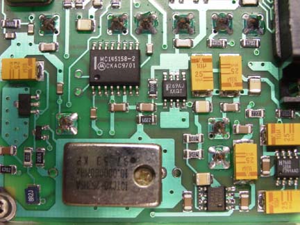
e) There is a proprietary protocol that the I.F. processor uses to communicate to the processor, so a standard MicroChip PIC 16F84A-04/P micro-controller was chosen to program the Motorola MC145158 synthesizer chip on power up. The loader program was written by Sam - K6VLM and provided to SBMS for this project. The new PIC 16F84A-04/P micro-controller board is now installed in the synthesizer box in the space vacated by the old TCXO.
f) The output amplifiers were re-tuned to produce an output power of 60+ mW, down about 10 mW from the original 70 mW L.O. output.
Transmit Module -
The transmit module required several modifications. The I.F. input circuit was modified to add a MAR-4 MMIC amplifier instead of the '420' programmable attenuator and biased appropriately. The I.F. filter was re-tuned to 3.072 GHz from 3.775 GHz. The L.O. doubler was re-tuned for a 10.560 GHz input/21.120 GHz output to the mixer. No re-tuning of the output filter was necessary. It was determined that the optimum voltage to the output GaAsFET's was +5 volts.
Success!! - With +7 dBm I.F. input at 3.072 GHz, the power output at 24.192 GHz was over 100 mW! The saturated power output was measured at 145 mW!
I.F. Processor Module -
This module is removed and is not used. Instead, a second converter module is built using a QualComm 3036/3236 Rectangular Synthesizer board (located at "http://www.ham-radio.com/sbms/sd/rplldoc1.htm") programmed to 2.640 GHz, and a Mini-Circuits SKY-5G mixer to convert the 3.072 GHz I.F. to 432 MHz. The converter board (designed by K6VLM) uses a Pin Diode switch go between transmit and receive (no relays!). The QualComm 10 MHz TCXO is shared between the 2.640 GHz QualComm Synthesizer and the 10.560 GHz Synthesizer.
Receive Module -
The Receive Module has been finalized, the modification required was to modify the receive I.F. filter to 3.072 GHz and tune the multiplier.
Power Supply -
The original Power Supply is removed and will be replaced by a 12 volt input supply delivering all necessary voltages (+12, +5 and -5 volts).
5. Next Steps -
First, to build the second prototype (the synthesizer is finished and the transmitter is about 50% complete) and complete the documentation and web site. Secondly, to put together kits and documentation to have a first run at building three systems by Doug - K6JEY, John - KJ6HZ, Kurt - K6RRA, Ken - WB6DTA and Bob - W6SYA. Thirdly, to be able to provide kits (in a quantity buy to get better prices) to SBMS members who have already purchased P-Com units and want to get on 24 GHz SSB as soon as possible and to others later.
Sam - K6VLM has provided the engineering modifications, micro-controller programming and will be providing the final tuning modifications for the Receive Module as well as P.C. Board designs for the micro-controller, second converter and transmit and receive power supply bias boards.
Dave - WA6CGR has provided the P-Com units (ODU's and Antennas) and will be providing the 2nd prototype and design verification, parts kits (including pre-programmed micro-controllers), SMD components (resistors, capacitors, micro-controller chips, SMD crystals, mixers, etc.), documentation (photos, conversion instructions, web site), etc.
6. Acknowledgements -
I would like to thank Sam - K6VLM for all of his continuous efforts, Hiro - KE6IDA, Doug, K6JEY, John - KJ6HZ, Kurt - K6RRA, Chuck - WB6IGP, Kerry - N6IZW (and I'm sure others) for their input, suggestions and putting up with us on the radio. This has been and will continue to be an exciting and intense SBMS project that everyone will be able to participate in!