This matching transformer will enable you to use your hi efficiency HF mobile screw driver antenna to have a much better match without using an antenna tuner. I used one on my Ford van quite effectively. It is now installed on my Surburban and works very nicely. Installation pictures of antennas link.
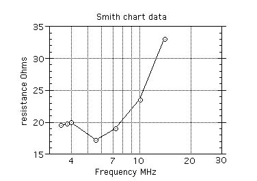
See impedance plot of typical HF mobile antenna mounted on vehicle and measured with a HP8714ES network analyzer. These points are resistive and occur at resonance. It was decided to concentrate on the lower bands since they are substantially lower impedance than the upper ones. Mobile antennas on 21 MHz and up are pretty close to fifty Ohms. Besides that, we are headed for the solar minimum.......
![]()
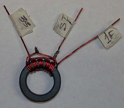
#20 Ga buss wire, Core = FT-114-61
First pull wire straight and tight to remove kinks and bends. Use
color coded wire, I used all Red....hi Wind 5
turns (old picture shows 6) of 3
parallel wires tight & close, #20 Ga, label each winding with
tape ( it helps). Prove each winding with Ohm meter (it helps).
![]()
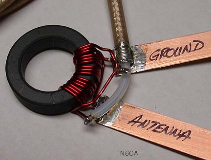
make "tap point" connections according to the schematic above: 1S to 2F, and 2S to 3F. twist several times. Keep windings close together on core.
cut off excessive leads. Be sure to label them per the schematic to minimize confusion.
![]()
Lead junctions are spaced apart for clearance of Copper ribbons
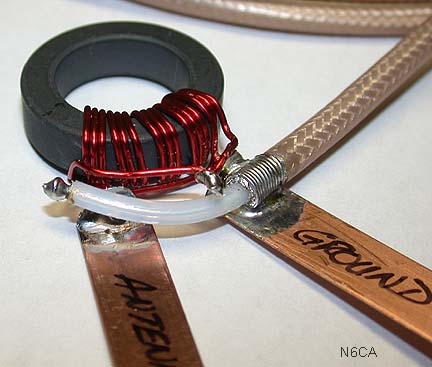
Close up of ribbon attachment.
Ribbon leads and coaxial cable attachment RG142 ptfe.
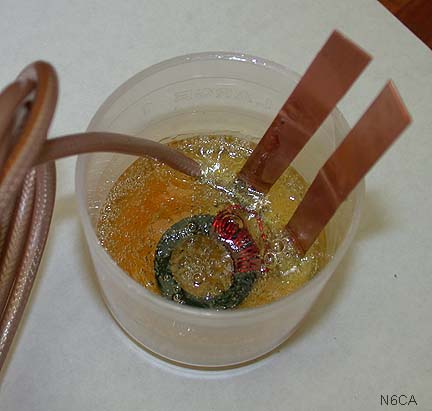
Two dual tube 5 minute epoxy used for potting the entire assembly approximately 2.5 inches in diameter. Hole drilled in epoxy for mounting.
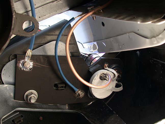
Complete assembly, painted and mounted under rear bumper of Surburban.
See: HF mobile antenna pictures for mounting details.
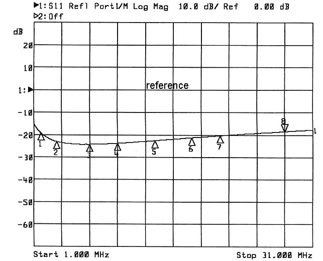
Back to back (two identical xfmrs) swept insertion loss show less than .05 dB loss so these should easily handle several hundred watts. Smaller cores, 0.5 inch diameter could be used without any problems. The network analyzer was run on the screw driver antenna mounted on the Ford van and characterized. It measured approximately 25 Ohms everywhere from 3.5 Mhz to 20 MHz. I even tried full size 40 meter quarter wave radials and the impedance didn't change. An interesting experiment anyway.
73 N6CA