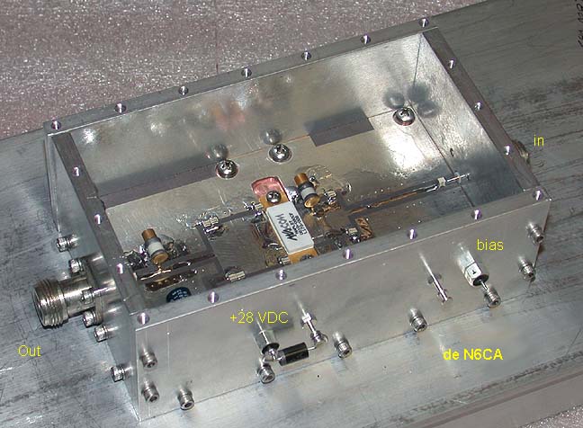
Final amplifier configuration using the M/A-COM RF Power Innovations MAPLST0810-090CF:
Data sheet for the 90 watt transistor
Assembly files and app notes for this amplifier will be available here shortly..
>90 watts output with 1.6 watts input
+28 VDC at 5.7 amps, final numbers will be up when data is taken.
1/4 inch walls were used for box so there would be enough thickness for easy cover attachment. Entire assembly is attached to 19 inch heat sink only using the (8) #6-32 screws and minimal thermal grease. Place amp on heat sink and rub around and remove to prove the thermal grease is making good contact over the entire contact surface. I use lots of screws in the housing since it's going on a mountain top; no leaks, in or out!
Below:
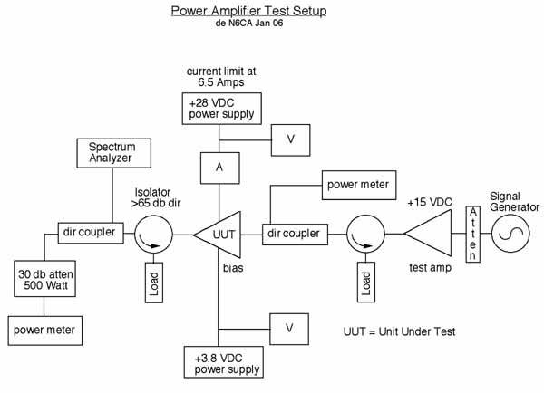
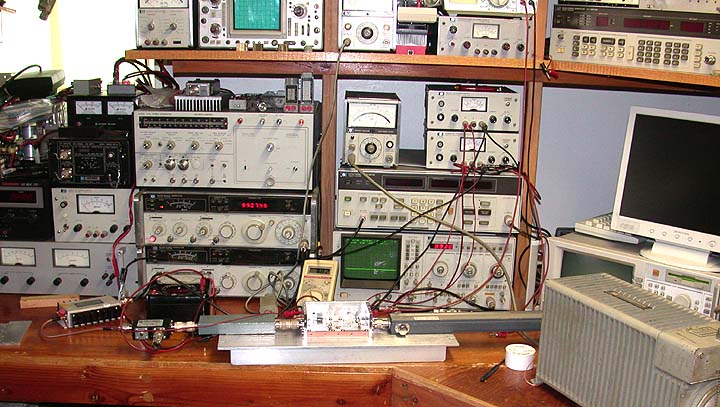
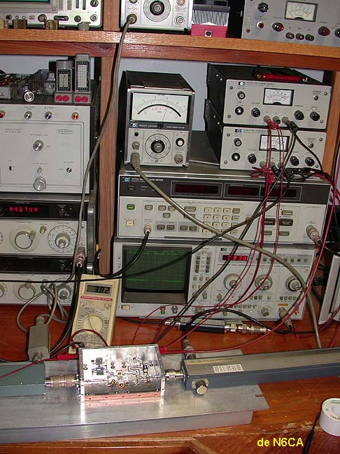
The only way to test a power amplifier for the first time:
Lighting off a new amplifier for the first time can be a little disconcerting. It doesn't matter what the power level is either. You must be cautious but confident in your test set-up, test equipment and in all of your measurements. Remember, no guessing! Full knowledge and documentation of all parameters is important as you turn it on for the first time, even if it is a proven design. Always current limit the power supplies slightly higher than you expect for normal operation. Then if something is wrong it probably won't destroy the amplifier. This amplifier should have used about 6 to 7 amps so the current limit was set at 6.5 amps. Running it from a 30 amp supply with no limiting could prove disastrous if something was wrong.
In this case I started out at 100 milliwatts of drive. This transistor is supposed to have about 17 db gain. That's an amplification of 50 times; 0.1 watt X 50 = 5 watts so no matter what, I should be OK. The entire test setup is assembled, all power supplies are set in voltage and proven with an external meter, current linits are set and proven with an external calibrated current meter ( when was the last time you proved your current meter is calibrated?). When all is set and ready to go, prove your drive level and complete RF set up by bypassing the UUT (Unit Under Test) with a coax adapter(s). The output power meter should give you the correct drive level and will verify that everything is hooked up correctly including the spectrum analyzer. If there are any low frequency oscillations, they will modulate the output signal of the amplifier and you can easily see them. Then reset all meters to the correct range for the increased levels from the UUT. Inserting the UUT will then be in a controlled setup. Apply DC voltages to the amplifier without RF drive and set the idling current. No should be no indications on the spectrum analyzer nor power meters. If there is then you probably some sort of instability. The spectrum analyzer will show you what's going on.
Once the amplifier was proven to be operate correctly at the 5 watt level then the power was slowly increased to the maximum of 1.6 watts. Incidently this drive level of 1.5 watts was limited so there was no way I could accidently go above that level. Inserting fixed attenuators in series with step attenuators makes this easy. As the drive level is increased observe all meters and verify that all is proceeding correctly. Once it is operating correctly and all of your tuning and tweeking is done, put some time on the amplifier while it's still in this test setup. I ran this amplifier at 90 watts output for about 20 minutes and touched all of the components for high temperatures after running it for a while. If of the tuning capacitors had been hot to the touch it would have indicated excessive RF currents in that part and a change would have been necessary. Before placing this repeater in mountain top operation I will run the the amplifier for a minimum of several hours at full output and place it in local service for a couple of weeks.
Always:
Measured and controlled drive in frequency and power level.
Input power meter for amplifier input return loss
Output power meter with calibrated cables, attenuators and directional coupler, +/- 0.1 db accuracy.
Spectrum analyzer to observe output for possible problems.
Meters to monitor voltage and current on ALL power supplies, prove that your voltage and current meters are calibrated as well.
below: typical minimum amplifier test setup
NO guessing allowed! I'm good at hoping and guessing too and it doesn't help at all......!
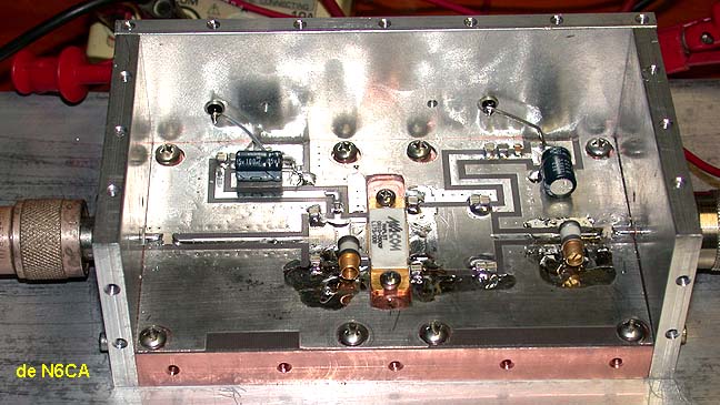
Construction of amplifier:
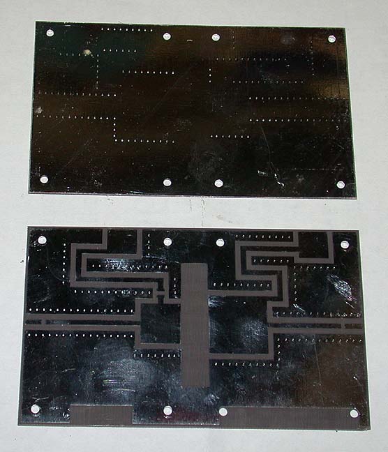
below: Taconic Er=2.55, 0.032 ptfe board, double sided copper, plated thru holes for vias (grounds)
front and back
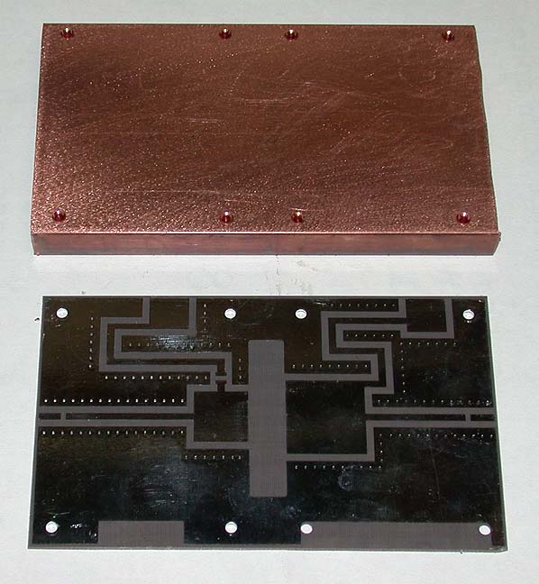
below: Copper block, 1/2 inch X 3 inch bar stock, rough cut to start with. Holes are tapped to allow easy attachment of PC board to block while soldering in place.
What's the reason for the Copper block? To spread the heat out for better cooling of the transistor
and
to establish excellent ground returns for the entire board by soldering it completely to the Copper block. Using screws alone will NOT establish good enough ground returns for the transistor, the matching components and the in and output connectors. Don't try any short cuts here as it will only give you mucho headaches!
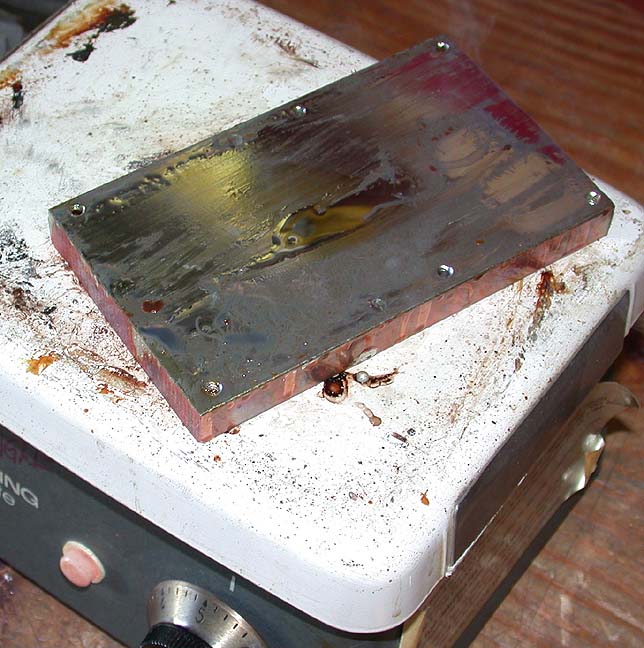
Copper block set on hot plate and tinned with Kester 44 solder
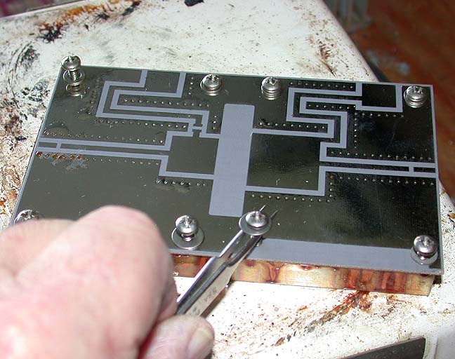
below: Place PC board on hot Copper block, (resist the temptation to grab the block) Insert stainless steel screws screws with tweezers (stainless steel) using large flat washers under screw heads.
below: Carefully tighten to compress board to Copper block. Do not over tighten.
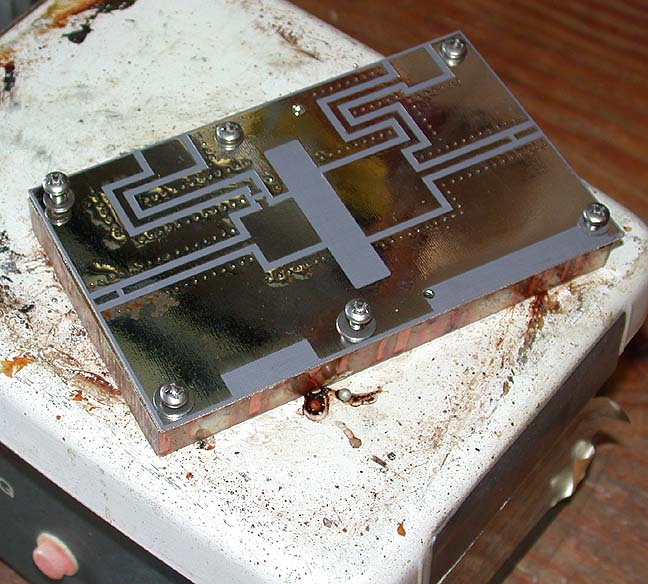
Remove assembly and let cool. If portions of board haven't compressed fully, carefully place aluminum blocks and weights on board until cool.
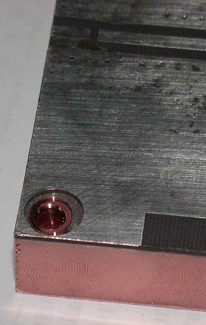
below: Machined edges and flattened bottom on mill. Transistor mounting slot is also machined
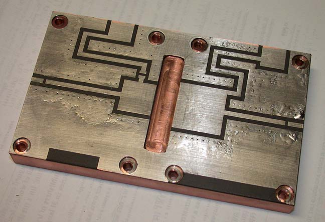
below: Original tapped screw holes are drilled out to allow screwing Copper block to heat sink. Easier to attach Copper block from this side of heat sink than trying to align the holes with the fins. It seems the fins are always in the wrong place. The PC board material is also removed around the screw holes to allow a secure fit of the screws to the block when mounted.