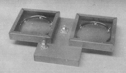 rings were attached with .125 dia Copper tubes
feeding thru the boxes
rings were attached with .125 dia Copper tubes
feeding thru the boxesThis is the original article that was submitted to QST and appeared in.QST April 1991 pp.28-30. Permission to reprint here from the ARRL
8 Feb 1988, updated Dec 2005
de N6CA
1296 MHz POWER AMPLIFIER COMBINING
Combining of two single tube cavity power amplifiers will deliver what most six tube amplifiers deliver, 400 watts at 1296 MHz.
The high power ring hybrid described herein is easy to build and works better than any hybrid money can buy. Its official name is ring-hybrid or 180 degree rat-race hybrid. Many articles have been written on its theory of operation.
PRINCIPLES
Basically, when a signal is applied to the input port, two equal in amplitude but opposite in phase signals will be produced at output ports, 0° and 180°. The isolated port should be terminated in a known good 50 ohm load.
When the hybrid is used for combining, the 0° and 180° ports are used as inputs, the input port is the sum of the input signals and the isolated port is the difference of the input signals.
The electrical circumference of the ring is 6/4 wavelengths. Figure 1 shows the basic splitting and combining scheme.
If two identical amplifiers are inserted between the hybrids, proper phase and amplitude will be maintained for power addition. If there are differences in the phase or amplitude response of the two amplifiers, this difference will appear at the isolated port of the output hybrid. It is for this reason that two power meters are needed for proper tuning of the combined amplifiers. One power meter is for the sum of the two amplifiers and one power meter for the difference of the two amplifiers. Six hybrids and four amplifiers have been used successfully for over 800 watts output.
CONSTRUCTION
Refer to Figure 2. A 3/16" outside diameter copper tubing is rolled around a 4 1/4" diameter form. This form must be as circular as possible. If possible, make a wooden cylinder on a lathe for bending the tubing. Tightly wrap the tubing while on the form. Wind several turns of tubing on the form and secure so it won't unwind. With a file, mark a line across all the turns of tubing. This will accurately set the length.
Now cut the tubing into individual rings. Chamfer the ends as they will be butt-joined and soldered. Carefully remove the pitch and spring-out of the rings by bending; this is the hard part. Check diameter and circularity by placing back on form. The rings must also be flat. After this is done then solder the butt-joint of each ring.
MOUNTING PLATE
The size of the enclosure is not critical as long as all side flanges are at least 1/2" from the ring. Depth should be greater than 3/4". As accurately as possible using a compass, mark the cover plate or box for your selected enclosure. This will also serve as a template. Drill all 1/8" holes only. Position the copper ring with tape to the inside of the plate and mark the connector center pin positions on the ring (four places). Accurately center-punch the ring at these four places and drill the 1/8" holes through the ring. Now the connector holes can be opened up on the plate to 1/2" diameter (counterbores are preferred). Don't use a chassis punch as it will warp the plate.
ASSEMBLY
Once all parts are made, check alignment before soldering. Mount spacers and connectors to enclosure. Clean and tin all parts. Position ring on the connector center pins. Temporarily install 1/16" spacers under the ring to set ring height above the plate (ground plane). Install "N" male adapters on all female connectors to keep alignment of the center pins. Now solder all ring-pin joints. Remove 1/16" spacers and clean all solder joints. Install cover on box. The unit is ready for testing.
TESTING
Testing of these hybrids should not be necessary if construction details were followed; there are no shorted connectors (internally) and the 3/16" diameter tube is spaced 1/16" above ground.
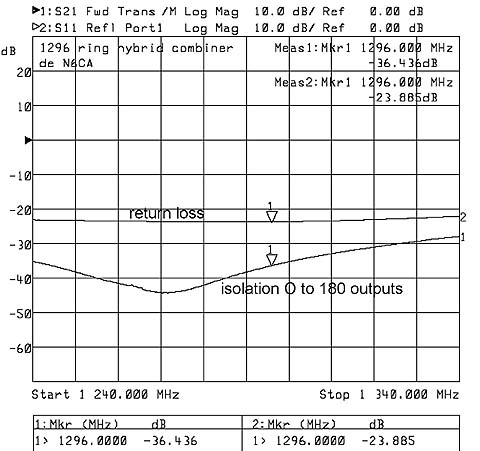
If you do desire to test the hybrid you must have some reasonably good test equipment. This should include a RF sweep generator, a log/detector with 40 dB of dynamic range (or spectrum analyzer), three (3) known (proven) good 50 ohm loads. Swept frequency response to measure hybrid isolation is the most accurate test you can run. Typical results at 1296 MHz are greater than 30 dB isolation. See: Isolation plot. This is measured between the "input" and "iso" port or between the two "output" ports. All unused ports during this test must be terminated in 50 ohms.
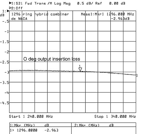
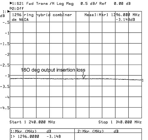
Output amplitude match can also be measured and should be less than 0.1 dB. Once again terminate all unused ports when measuring. See Netwaork analyzer plots: 0 degree output, 180 degree output
A crude but adequate test can be made with a clean 1 W transmitter. The problem is there are no clean 1296 transmitters or transverters on the market today. All put out enough extra "stuff" to possibly give confusing results, especially on a Bird watt-meter. These meters read power at virtually all frequencies and can be as much as 3 dB off in absolute accuracy when using the 400 to 1000 MHz slugs which everyone uses.
If you can indeed get a reasonably clean 1296 signal, feed it into the hybrid. Make sure the cover is on the hybrid. With a 50 ohm load on the isolated port and one output, measure power at the other output. It should be close to one-half the measured input power. Now remove the 50 ohm load from the other output. The power meter should not change in reading. Now try the same measurement on the other output port. Verify the 50 ohm loads you are using are really 50 ohms. If they are different then the test will not yield valid data.
Once the hybrids are checked out, the individual amplifiers have been checked out and tuned correctly, then the entire assembly can be integrated. Here are some MUSTS; the cable lengths from the hybrids to the amplifiers must be identical, both the input pair and output pair. Output connections are best made by using double "N" male and elbow adapters pointing up to the two hybrid inputs. This keeps the length identical and losses down. Fifty feet of RG-58 coax will provide a more than adequate high power intermittent duty dummy load for the output and input hybrid isolation loads. Typically they measure 20 dB return loss and 12 dB of attenuation and can handle a hundred watts of power for many seconds.
After interconnecting the hybrids, amplifiers, loads and power meters, the entire system can be tested. Start with very low drive power, less than two watts and low anode voltage on the amplifiers, approximately 400 to 500 VDC. The amplifiers were pre-tuned so they shouldn't change. Observe the difference meter nulled by minor adjustment of the anode control on each amplifier.
When the output is about what single amp produced under the same conditions (drive and anode voltage), the drive and anode voltage can slowly be increased. While learning how to tune the amplifier, proceed slowly and don't go for full output until you get a real "feel" for how it tunes.
Always make sure the amplifiers are peaked on the sum meter and nulled on the difference meter. Absolute maximum drive is 15 watts per amplifier and should not be exceeded. Once operating, always check tuning of the amplifier at about the 100 watt output level before going for high power. With water-cooling this amplifier can be turned on and will maintain greater than 400 watts out; key down for a least a half hour without retuning.
I combined three ring hybrids for the four cavity amplifier I built many years ago:
rings were attached with .125 dia Copper tubes
feeding thru the boxes
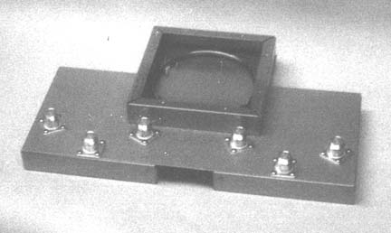
and input hybrid was constructed with SMA female connectors as well