This FET preamplifier has been around for almost 25 years. It is extremely reliable and can handle several watts directly into either the input or the output without failure. Noise figure is typically around 1 db and gain is about 13 db. It is unconditionally stable. It is also very re-produceable. Layout is not critical but it should follow the schematic in layout fashion. It is also wise to put it in an enclosure.
Noise figure bottoms out in the U310 from 12 to 18 mA which is between 1.0 and 1.5 db typically up to 144 MHz, and about 1.8 db a 222 MHz, which are all you really need for virtually all terrestrial applications. EME is a different story. Output compression point is about +12 dbm. The U310 is the top of the line in it's family. It's in a metal can where the gate is the case. The E310,309 & 308 will give a much worse noise figure. I usually mount them upside down for a shorter gate lead but you don't have to do that. Alignment is simple: set input capacitor mid range for 28 & 50 MHz and near maximum for 144 & 222 MHz and tune the output for max gain. That will put you very close to optimal alignment. A noise figure meter will help but it isn't really needed in most cases as you will be close. In cases where you want to put a great little preamplifier in your favorite radio merely build this critter on a very small board and use hard soldered coaxial cables for the interfaces. I have built them as small as 3/4 inch square.
For your info, I only use U310 preamplifiers on all bands from 50 thru 222 MHz for terrestrial weak signal operating. When used in conjunction with good band pass filters you can bring any good radio up to its best sensitivity withour blasting it with 24 db gain from a GaAs FET preamplifier. Your radio won't handle that much gain anyway. Stick with the 12 db gain and you will be much happier with your systems performance. These FET preamplifiers are very forgiving to accidental over-drive. They will handle at least 3 watts CW to the input and 25 watts directly into the output without damage (amazing).
|
frequency |
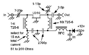
C in |
Input Inductor |
Output Inductor |
C out |
Cap-drain |
Bypass cap |
RFC |
|
28 MHz |
15-60p |
20 turns T25-6 #30 |
24 turns T25-6 #30 |
10p |
1-10p |
.01 micro F |
10 micro H |
|
50 MHz |
7-25p |
13 turns T25-6 #30 |
16 turns T25-6 #30 |
3.6p |
1-10p |
2700p |
5 micro H |
|
144 MHz |
3-15p |
5 turns #18, 1/4" dia |
5 turns #18, 1/4" dia |
2p |
1-10p |
200p - 300p |
2 micro H |
|
222 MHz |
1-10p |
3 turns #18, 1/4" dia |
3 turns #18, 1/4" dia |
2p |
1-10p |
100p |
1 micro H |
performance plots to follow soon.......