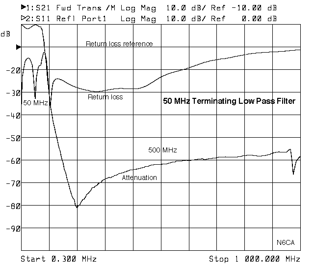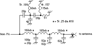
This low pass filter, adapted from the ARRL handbook, terminates all harmonics from the 2nd to above the 10th harmonic in a better than 15 db return loss load. It also functions as a 0.1 db insertion loss low pass filter. It will give better linearity to any transistor amplifier. It eliminates all harmonics from reaching the antenna and keeps them from being reflected back to the amplifier or preceeding stage. It will also improve interstage linearity and stability. I have measured approximately 3 db of improvement in third order products at the 100 watt level using this filter compared to an identical low pass filter without the terminating section. More tests will be forthcoming as well as the 1 KW design.
In short....a something for nothing filter.

Floor limit in this case due to enclosure cross talk. Shielding or compartments will push the floor much farther down, >-100dbc. N connectors are recommended for sustaining the good return loss of the filter. The 3 pf capacitor can be tweeked to improve the higher frequency return loss if desired. The design values include 4 nH of inductance for the dipped mica capacitors. The hi pass filter coils are #24 gauge buss wire wound on drills for size. Keep all leads short and make sure there is a good ground sheet for the return of all RF currents throughout the entire enclosure. The enclosure should also have good tight covers to prevent leaks. The low pass filter is tuned by bending the 5 turn coils. No capacitor tuning is necessary nor desired.

The best way to assure a good (proven ) 50 Ohm load for the hi passed port is to mount a connector and bring the port outside of the enclosure. That way you can control the impedance of the load (no guessing). I would suggest one of the 1 watt N connector loads available today from various companies. Also. use quality connectors for the input and output. SO239 connectors are not quality connectors! If you run an external connector for the hi pass load then slightly better tuning can be obtained. If you assume the harmonics of your transmitter are worst case 30 db down then: 100 Watts =+50 dbm & -30 db then =+20 dbm or 100 milliwatts. A small low power load will work nicely. However don't be fooled by the low power requirement. Carbon composition resistors won't provide a good enough 50 load unless you use a 1/8th watt package with no lead length. Several chip resistors in parallel will work fine, (4) 1/8th watt 1206 package 200 Ohm resistors will work fine.
Copyright 1June98 ER Angle