30 Watt 50 MHz beacon de N6CA 02.2001 updated
Beacons play an important part in studying propagation. They are great indicators for determining band openings but, they can also be a nuisance if you live near one. In North America we have too many beacons! Throughout the rest of the world there aren't enough beacons on six meters so if you live anywhere outside of North America please built more six meter beacons.
Many of beacons of this design are presently in use around the world today. The following beacon design is reproducible, highly efficient and clean. It runs class C power amplifiers in the final two stages and has an efficiency of about 65%, +13.4VDC at 3.6 Amps
The oscillator is loaded by a 7 to10 db attenuator and is followed by a high gain class A buffer amplifier with a good 50 Ohm input impedance. Discernable oscillator chirp is virtually eliminated using this scheme. Don't get me wrong, chirp has its advantages. The human brain can hear a weak chirpy signal much better than a stable one. The problem is we all think it just sounds bad.....Chirp has personality!
The buffer amplifier drives a broad-banded MRF476. It turns out this is a more stable design in Class C operation being broadband. It also performed well biased to class AB operation but the additional gain was not needed here. The MRF476 input and output networks have been simplified to bifilar transformers for step down plus some input "tweeking" capability. The networks were originally trifilar transformers.
The MRF477 is a great transistor. It has quite a bit of gain and is very efficient. It and the MRF476 come in TO220 packages so they are very easy to heat sink. That means you don't have to mill or drill away any heat sink fins to mount them . . . . a big plus! Low frequency feedback networks are included to assure stability at a few MegaHertz.
One of the biggest deficiencies with many power amplifiers today is their lack of adequate low frequency (several MegaHertz) filtering and de-coupling of the supply voltages. Many times a year we all receive the benefits of a low frequency oscillation in a mountain top power amplifier. . . . . There is small, medium and very large capacitors and low frequency chokes in these power amplifier stages. This eliminates the low frequency path through DC supply leads to the other stages.
A terminating low pass filter is included to keep all harmonics from ever leaving the enclosure. This filter has proven it self over the years as a great way to place a good broad band 50 Ohm load on any amplifier.
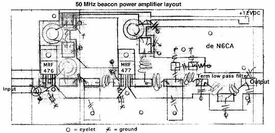
The layout is pretty straight forward if you merely follow the schematic. Below is the power amplifier-filter layout. Be sure and place all boards in a well shielded enclosure with many screws. Put the power amplifier in a separate box from the oscillator-buffer.
power amplifier layout (32k jpeg)
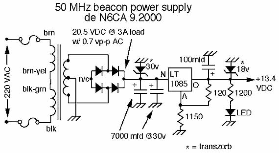
Power supply schematic (32k jpeg)
If you place a beacon on any crowded RF site be sure to follow it with a low loss band pass "cavity" or resonator to keep most other frequencies out of the power amplifier stage. Any power amplifier is a great mixer and will easily generate mixed signals for all the world to hear. Isolators are expensive and you don't normally see them this low in frequency but if you are running any VHF and higher beacons then be sure to use good communications site engineering practices and use filters and isolators. If everyone ran an isolator and band pass filter on their transmitters we would all have much less interference.