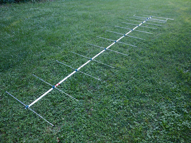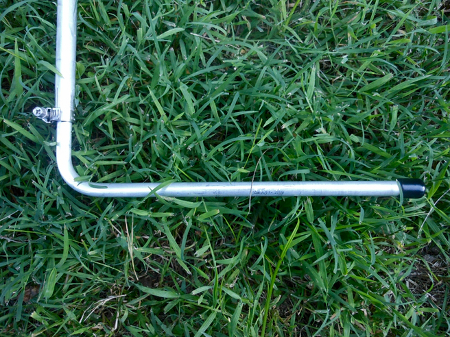
The InnovAntennas 88-DES-14 is a 14-element Yagi on a 219″ boom. The driven element ends are bent.

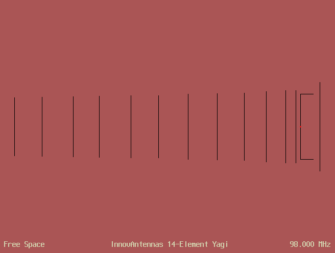
I modeled the antenna with the AO 9.53 Antenna Optimizer program. This image shows the antenna geometry. The red dot is the 75Ω feedpoint.

Wes Tewmey assembled this antenna in Watertown, Tennessee.

The driven element length is adjustable. I used the "starting point" length from the assembly manual. I did not model dielectric loss or loading due to the plastic end caps all elements use.

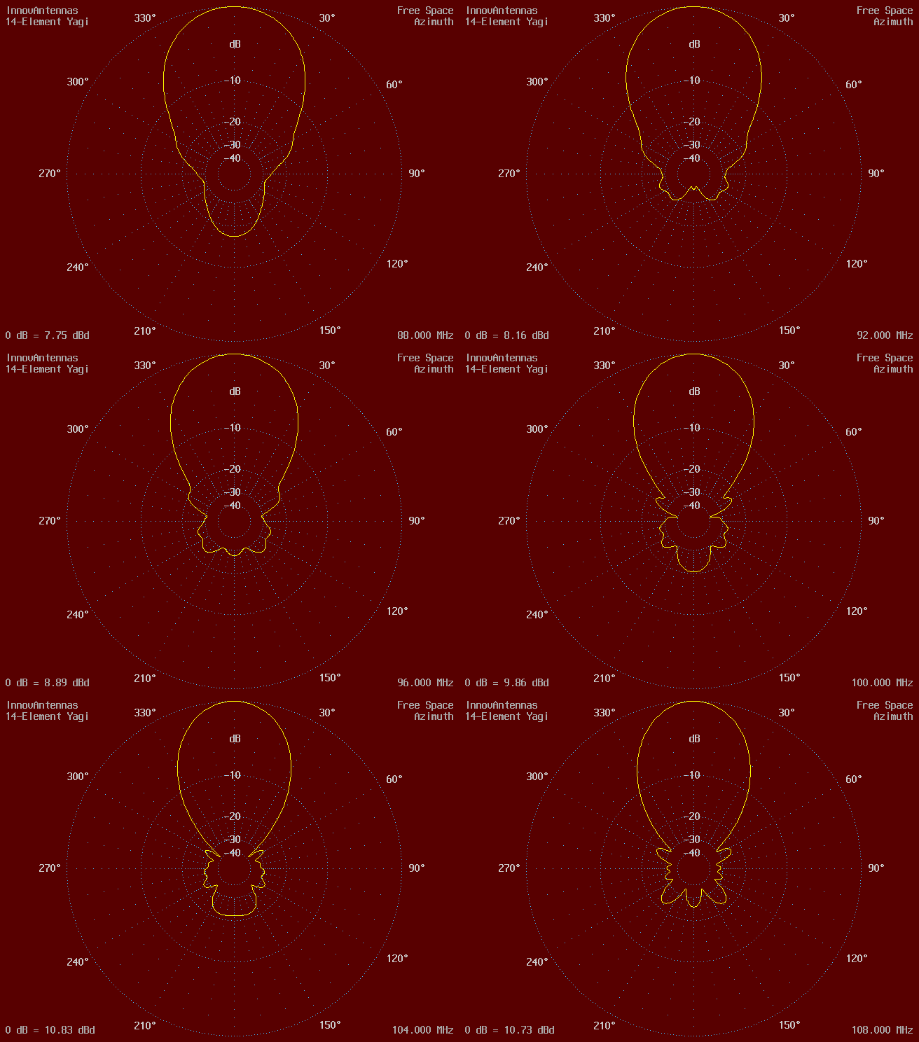
Click pattern to denormalize
Calculated performance is for 28 analysis segments per conductor halfwave. Forward gain includes mismatch and conductor losses. F/R is the ratio of forward power to that of the worst backlobe in the rear half-plane.
Frequency  Impedance    SWR   Mismatch  Conductor   Forward    F/R
   MHz        ohms             Loss dB   Loss dB   Gain dBd     dB
    88     56.4+j11.0   1.39     0.12      0.02      7.75     16.91
    89     71.8+j11.5   1.18     0.03      0.01      7.91     20.91
    90     83.2+j7.5    1.15     0.02      0.01      7.99     25.66
    91     89.7+j2.3    1.20     0.04      0.01      8.06     26.94
    92     92.6-j1.8    1.24     0.05      0.01      8.16     26.18
    93     93.2-j4.6    1.25     0.05      0.01      8.30     25.69
    94     92.4-j5.5    1.24     0.05      0.01      8.47     24.79
    95     91.5-j4.7    1.23     0.05      0.01      8.67     24.18
    96     90.9-j3.0    1.22     0.04      0.01      8.89     23.91
    97     91.0-j0.8    1.21     0.04      0.01      9.12     23.98
    98     91.7+j1.0    1.22     0.04      0.01      9.36     22.89
    99     92.6+j1.7    1.24     0.05      0.01      9.60     21.53
   100     92.6+j1.1    1.24     0.05      0.02      9.86     20.55
   101     90.4-j1.0    1.21     0.04      0.02     10.12     19.99
   102     85.9-j1.2    1.15     0.02      0.02     10.39     19.97
   103     79.1+j0.8    1.06     0.00      0.03     10.63     20.49
   104     72.9+j6.1    1.09     0.01      0.03     10.83     21.59
   105     69.7+j13.1   1.22     0.04      0.04     10.94     22.55
   106     70.8+j19.2   1.31     0.08      0.05     10.97     23.00
   107     75.1+j20.0   1.31     0.08      0.07     10.91     22.83
   108     85.0+j7.8    1.17     0.03      0.11     10.73     22.39
InnovAntennas 14-Element Yagi
Free Space Symmetric
98 MHz
18 6063-T832 wires, inches
x1 = 0			; reflector position
t2 = 4.6875		; DE tip position
x2 = 14			; DE position
x3 = 17.25		; director positions
x4 = 24.5
x5 = 38.375
x6 = 54
x7 = 73.625
x8 = 94.5
x9 = 115.375
x10 = 135.375
x11 = 158.125
x12 = 176.625
x13 = 199
x14 = 218.625
y1 = 31.875		; reflector half-length
u2 = 21.875		; DE fixed-section half-length
v2 = 46.22/2 + 0.1875	; DE adjustable-section half-length
y3 = 26.125		; director half-lengths
y4 = 26
y5 = 25.125
y6 = 24
y7 = 23.875
y8 = 23.5
y9 = 22.375
y10 = 22.5
y11 = 22
y12 = 21.5
y13 = 21.25
y14 = 20.75
1    x1   y1   0    x1  -y1   0    0.375
1    x2   u2   0    x2  -u2   0    0.5
1    x2   u2   0    x2   v2   0    0.375
1    x2   v2   0    t2   v2   0    0.375
1    x2  -u2   0    x2  -v2   0    0.375
1    x2  -v2   0    t2  -v2   0    0.375
1    x3   y3   0    x3  -y3   0    0.375
1    x4   y4   0    x4  -y4   0    0.375
1    x5   y5   0    x5  -y5   0    0.375
1    x6   y6   0    x6  -y6   0    0.375
1    x7   y7   0    x7  -y7   0    0.375
1    x8   y8   0    x8  -y8   0    0.375
1    x9   y9   0    x9  -y9   0    0.375
1   x10  y10   0   x10 -y10   0    0.375
1   x11  y11   0   x11 -y11   0    0.375
1   x12  y12   0   x12 -y12   0    0.375
1   x13  y13   0   x13 -y13   0    0.375
1   x14  y14   0   x14 -y14   0    0.375
1 source
Wire 2, center
 88–108 MHz